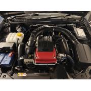
Ford Falcon Barra Sensor & Connector Quick Reference Guide
Over the last few years we have extended our range of connectors and parts to suit the Barra engine, so we decided to collate this handy cross-reference guide for anyone looking to replace any sensors or broken connectors. Where possible we’ve tried to list OE quality replacement parts & connectors for every part on the engine.
| Name | Sensor / Part | Connector |
|---|---|---|
| Power Steering Pressure Sensor | 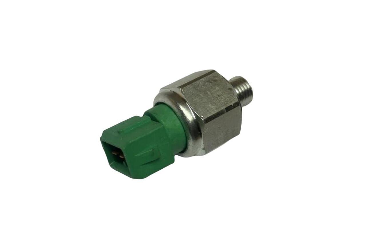 94BP-3N824-AA – suit BA BF Falcon | 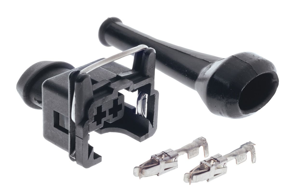 Connector & Pins | Pigtail |
| Knock Sensor | 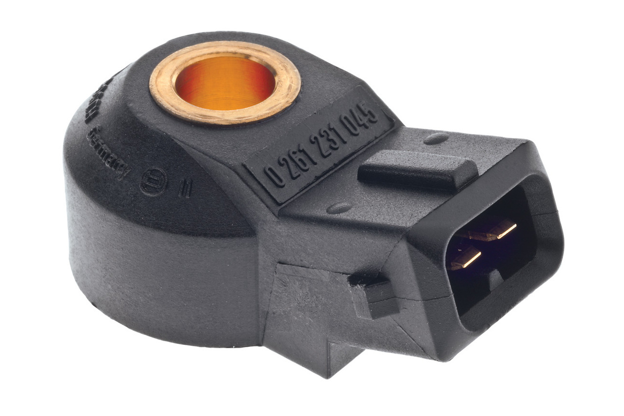 Bosch 0 261 231 045 – suit BA BF FG FGX Falcon | Connector & Pins | Pigtail |
| Oil Pressure Sensor / Sender | 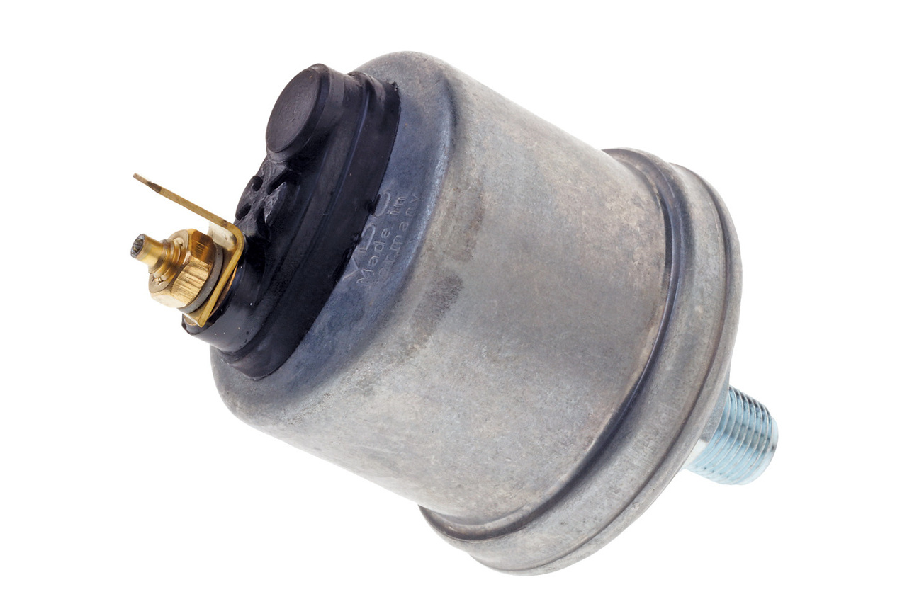 360-081-032-025C – suit BA BF Falcon 360.001 – suit FG Falcon | 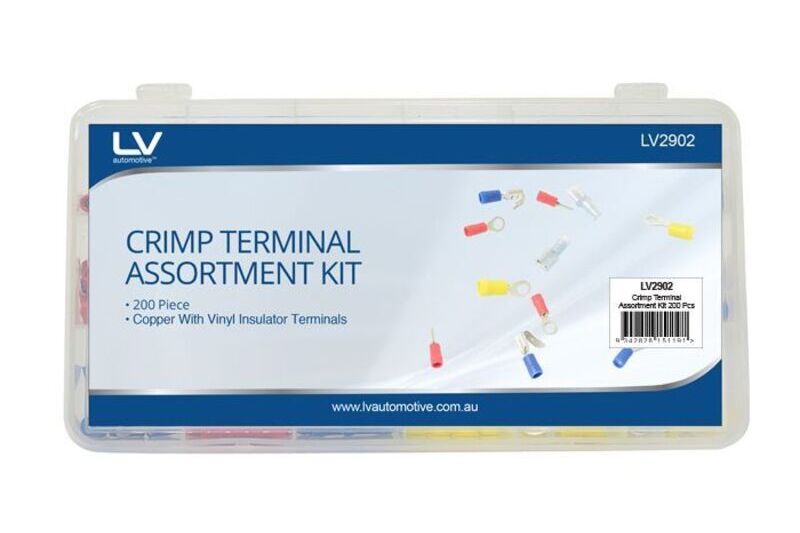 Generic Spade Terminal |
| Oil Pressure Switch | 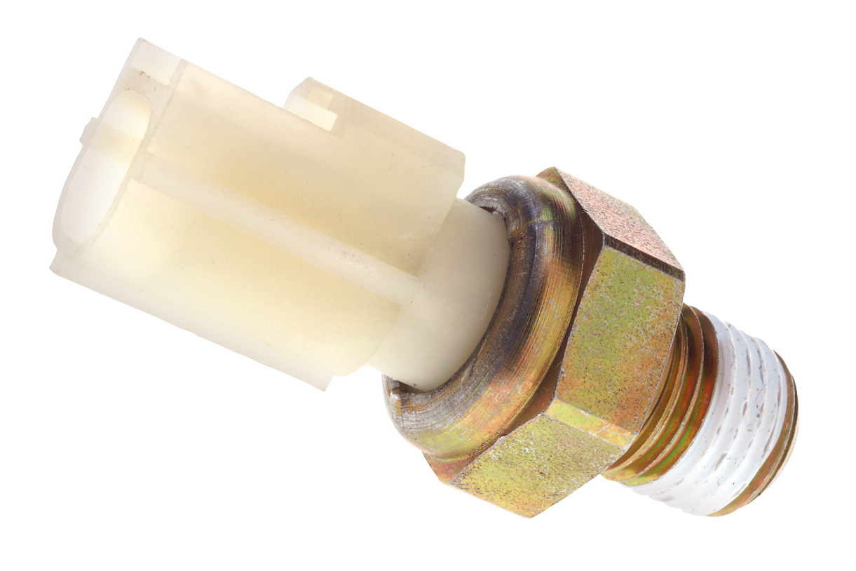 KS-1353 – suit BA BF FG FGX Falcon | 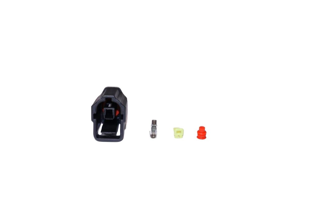 Connector & Pins |
| Oil Temperature Sensor |  TC6019 – suit BA BF FG Falcon | 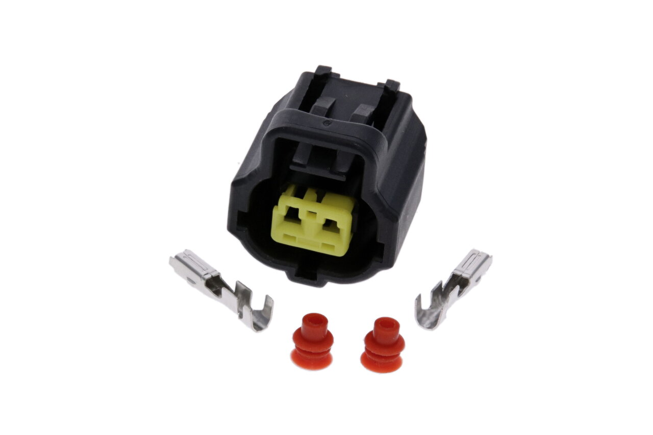 Connector & Pins |
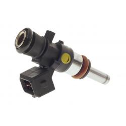
| Injectors | 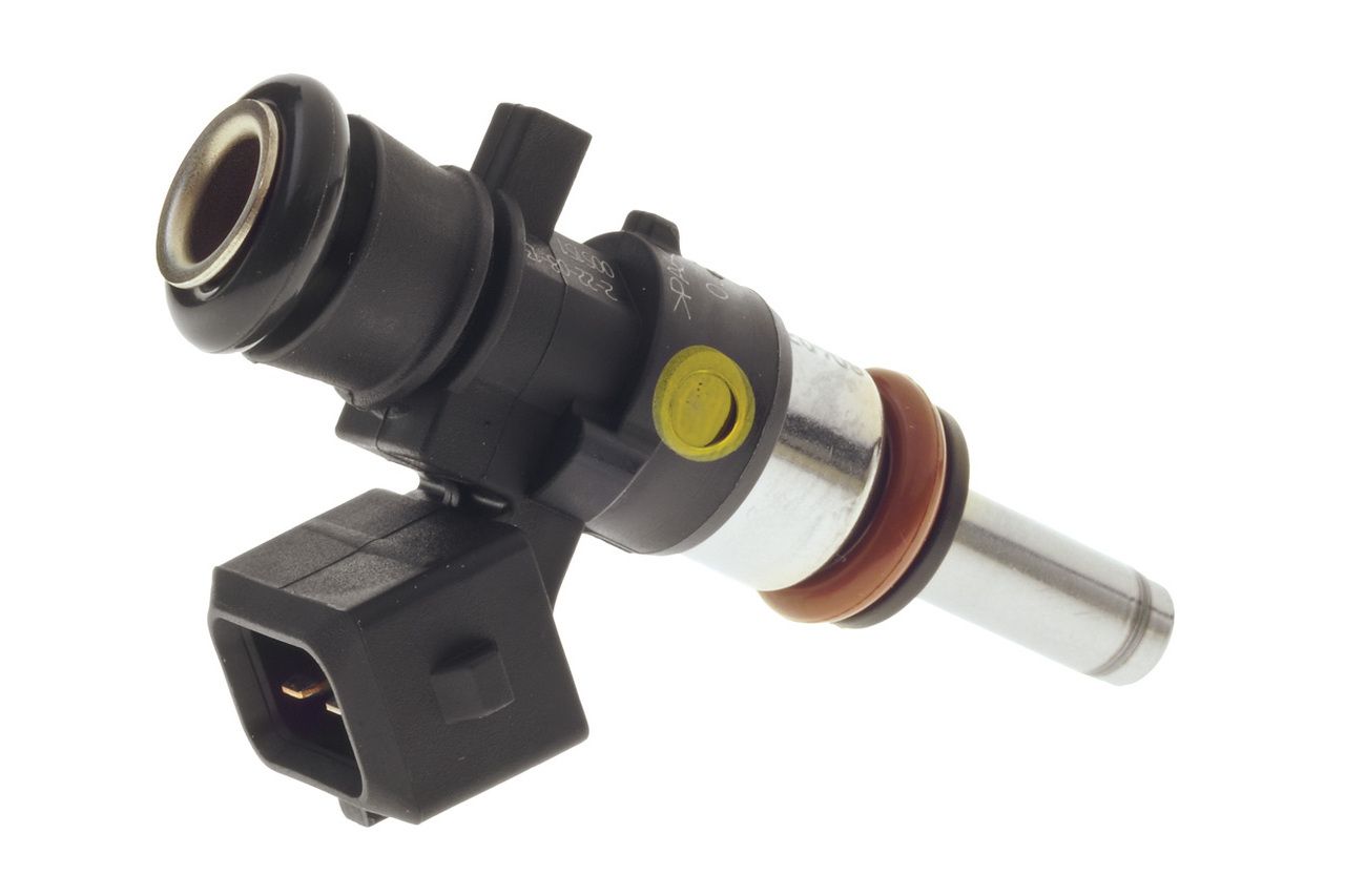 Bosch 0 280 156 123 – suit BA BF Falcon FIV9675 – suit FG Falcon Performance upgrade injectors, including: – Bosch 0 280 155 968 (BA/BF 98) – Bosch 0 280 158 040 (FG Turbo, BA/BF Turbo w/ Extensions) – Bosch 0 280 158 040 (FG NA+T) – Bosch 0 280 158 333 (BA/BF/FG 1650cc) | Connector & Pins | Pigtail |
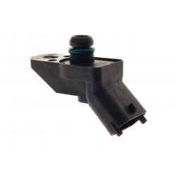
| MAP Sensors | 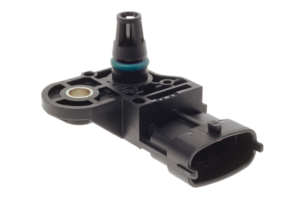 Bosch 0 261 230 027 – suit BA BF Falcon (N/A) Bosch 0 261 230 098 – suit BA BF Falcon (Turbo) Bosch 0 261 230 217 – suit FG Falcon (N/A) Bosch 0 261 230 128 – suit FG Falcon (Turbo) Bosch 0 281 006 051 – 4 Bar Performance Upgrade to suit BA BF FG Falcon | 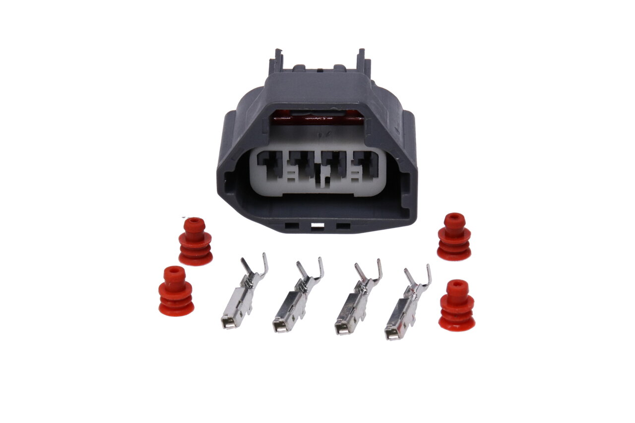 Connector & Pins – suit AU BA BF N/A & FG Turbo (Bosch 0 261 230 027 & Bosch 0 261 230 128) Connector & Pins – suit BA BF Turbo & FG N/A (Bosch 0 261 230 217, Bosch 0 261 230 098 & Bosch 0 281 006 051) |
| BA BF Throttle Pedal (APS) | PEDAL COMING SOON Use WIN008 for GQ GU Patrol conversions Use WIN002 for EA-AU Falcon Conversions | 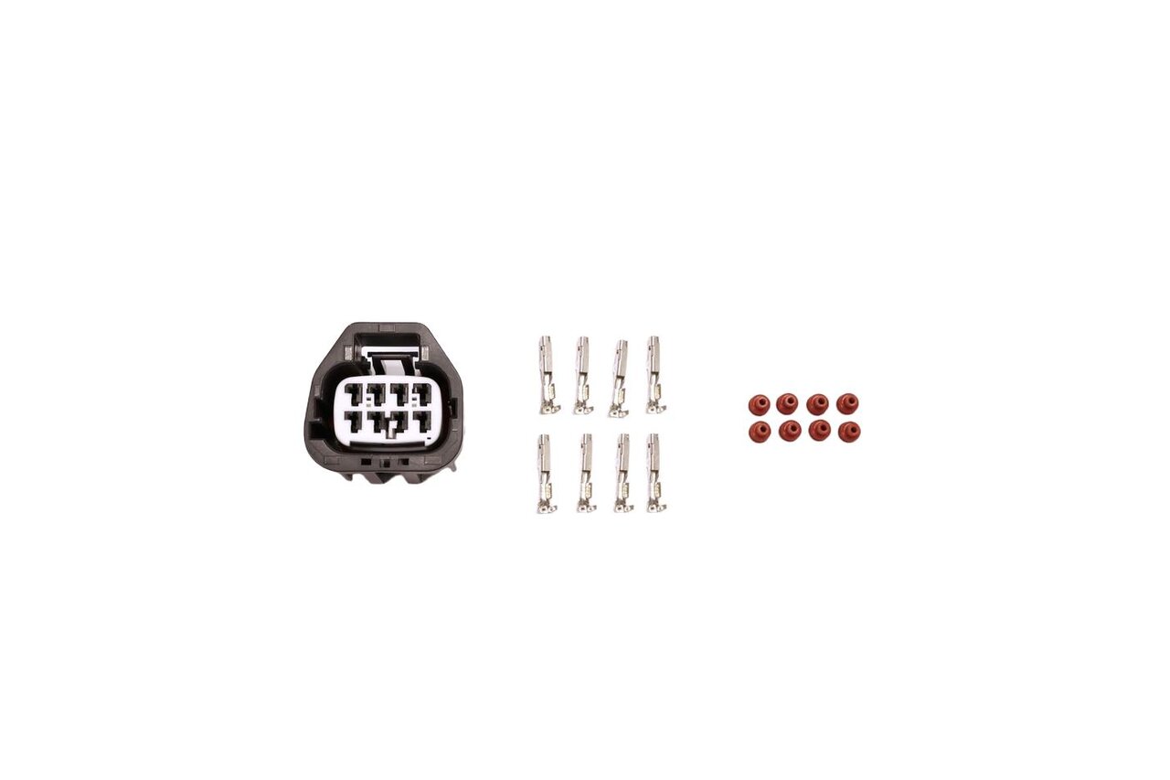 Connector & Pins |
| FG Throttle Pedal (APS) | PEDAL COMING SOON Use WIN009 for GQ GU Patrol conversions | 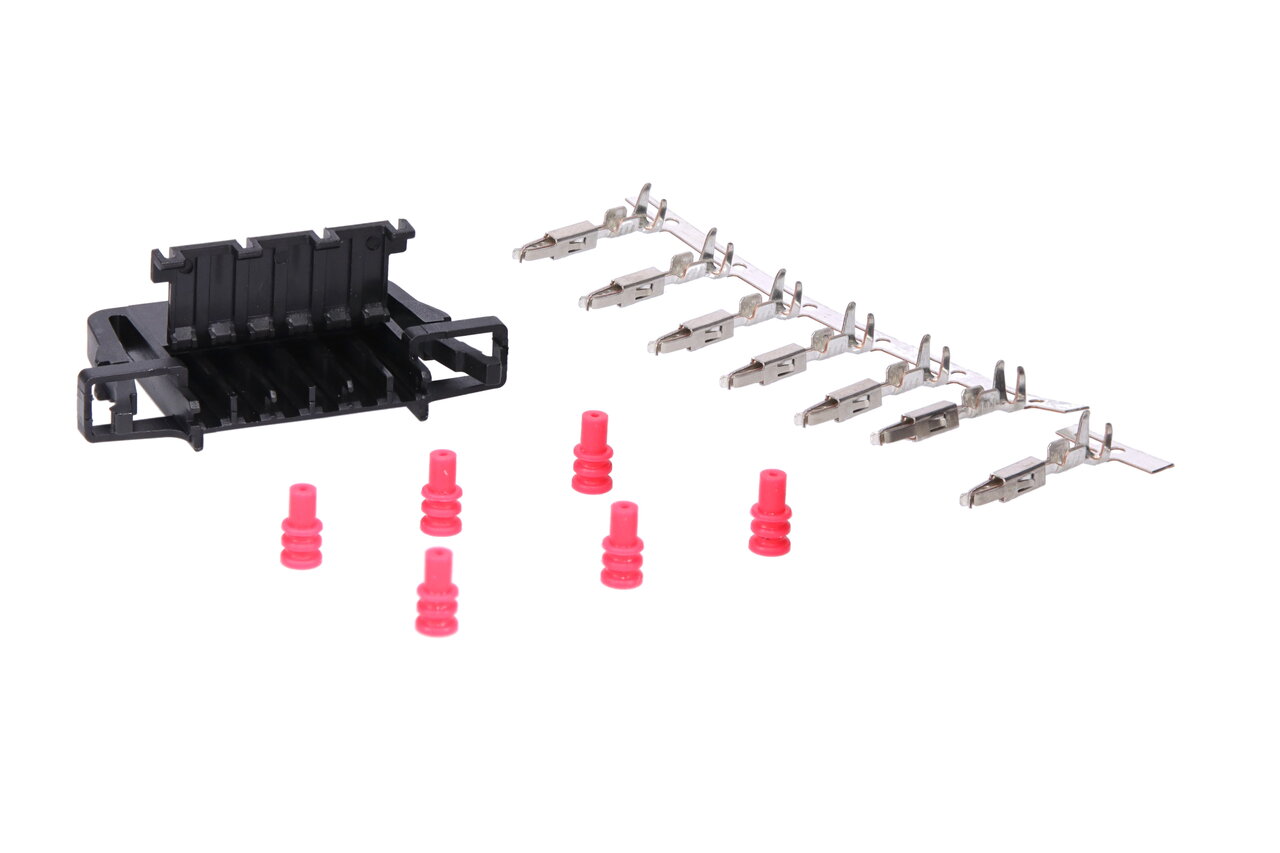 Connector & Pins |
| Boost Pressure Sensor | 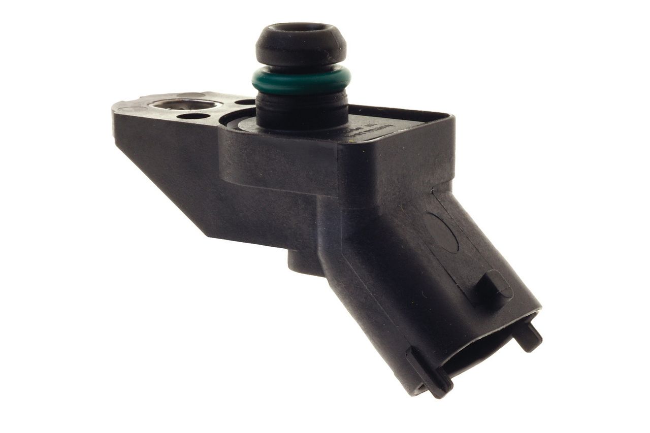 Bosch 0 261 230 029 | 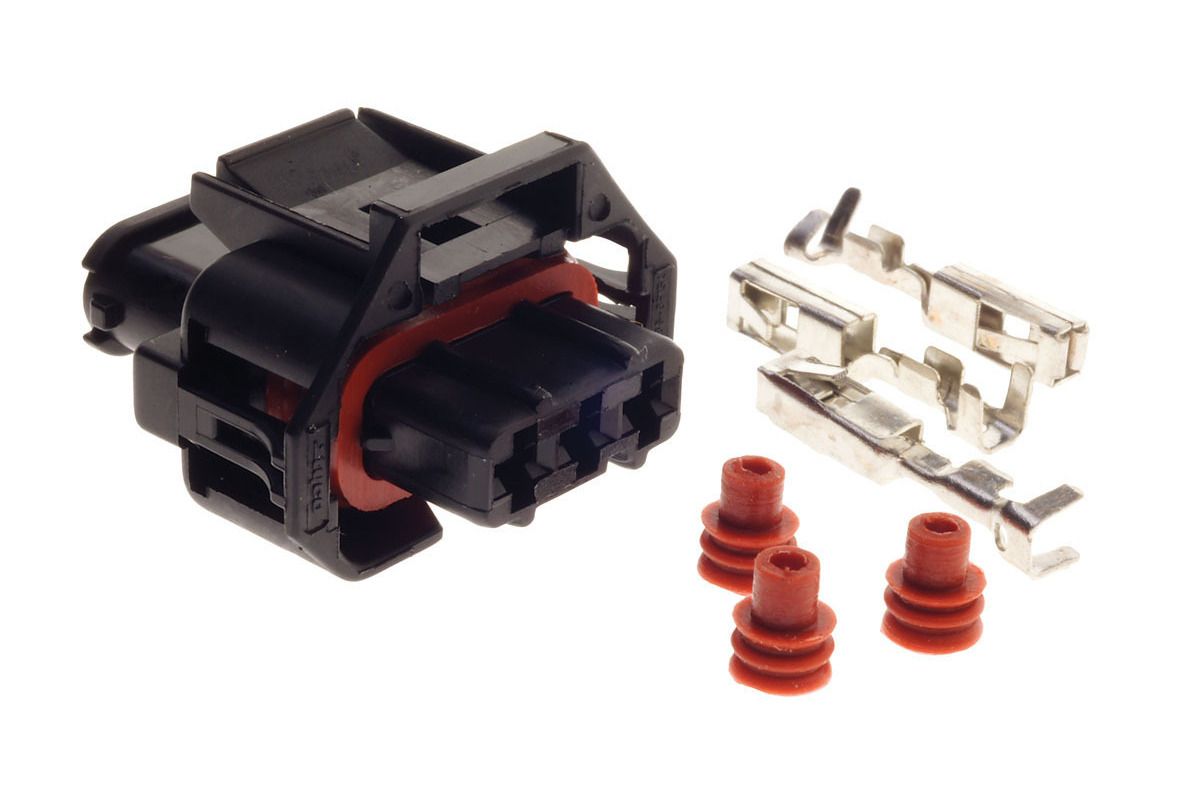 Connector & Pins |
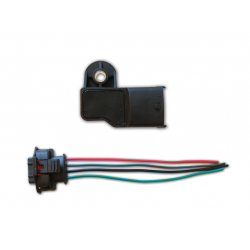
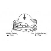
| Crank Angle Sensor | 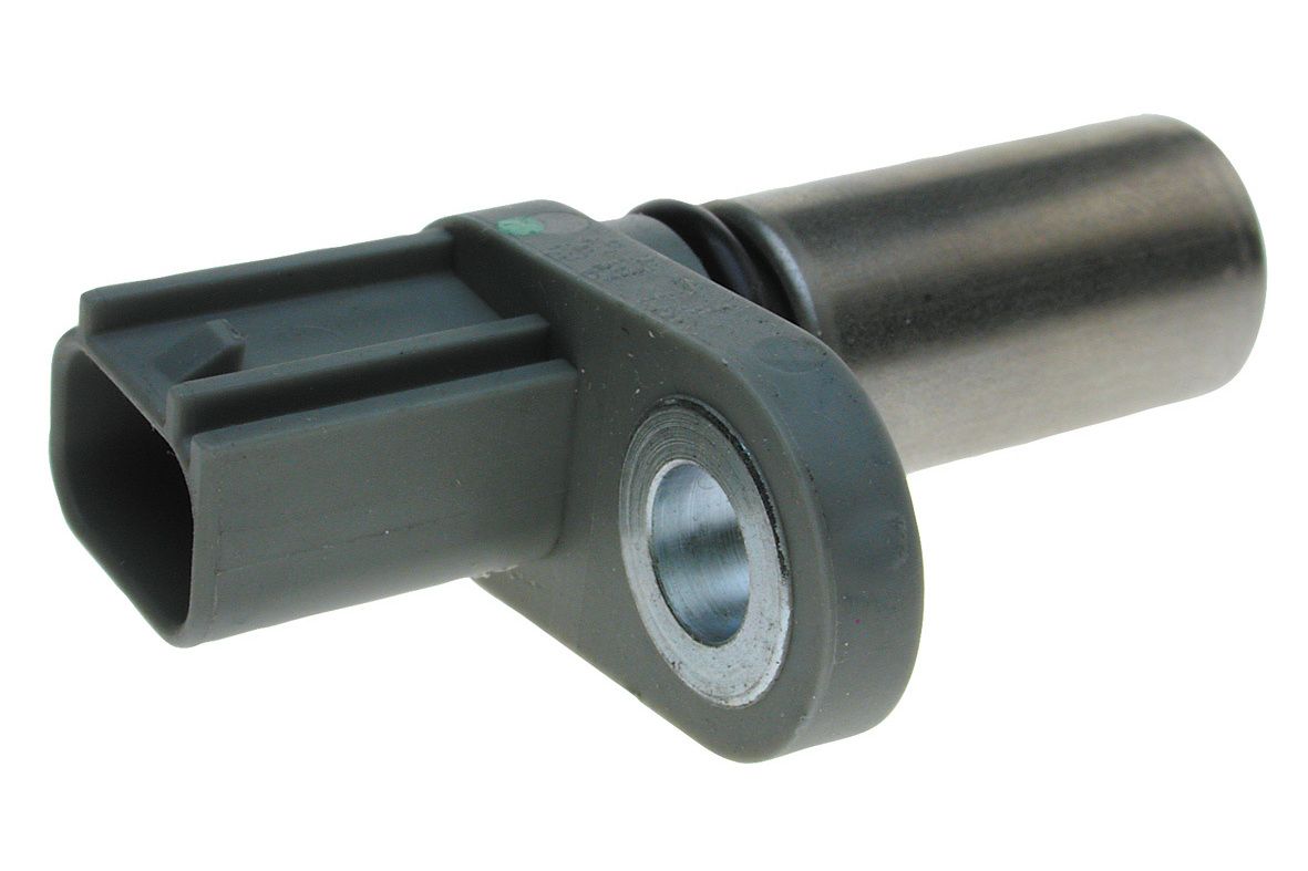 EH0196 | 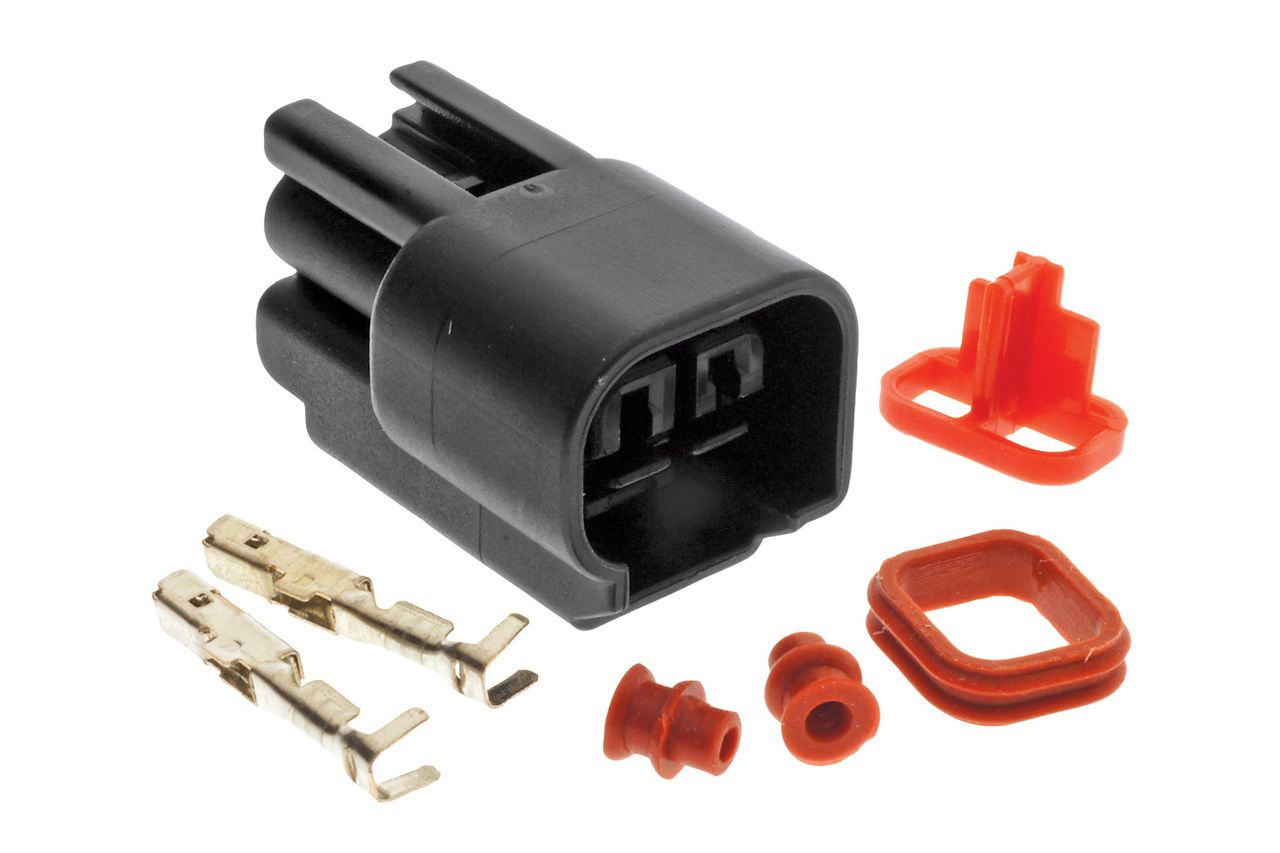 Connector & Pins |
| Cam Angle Sensor | 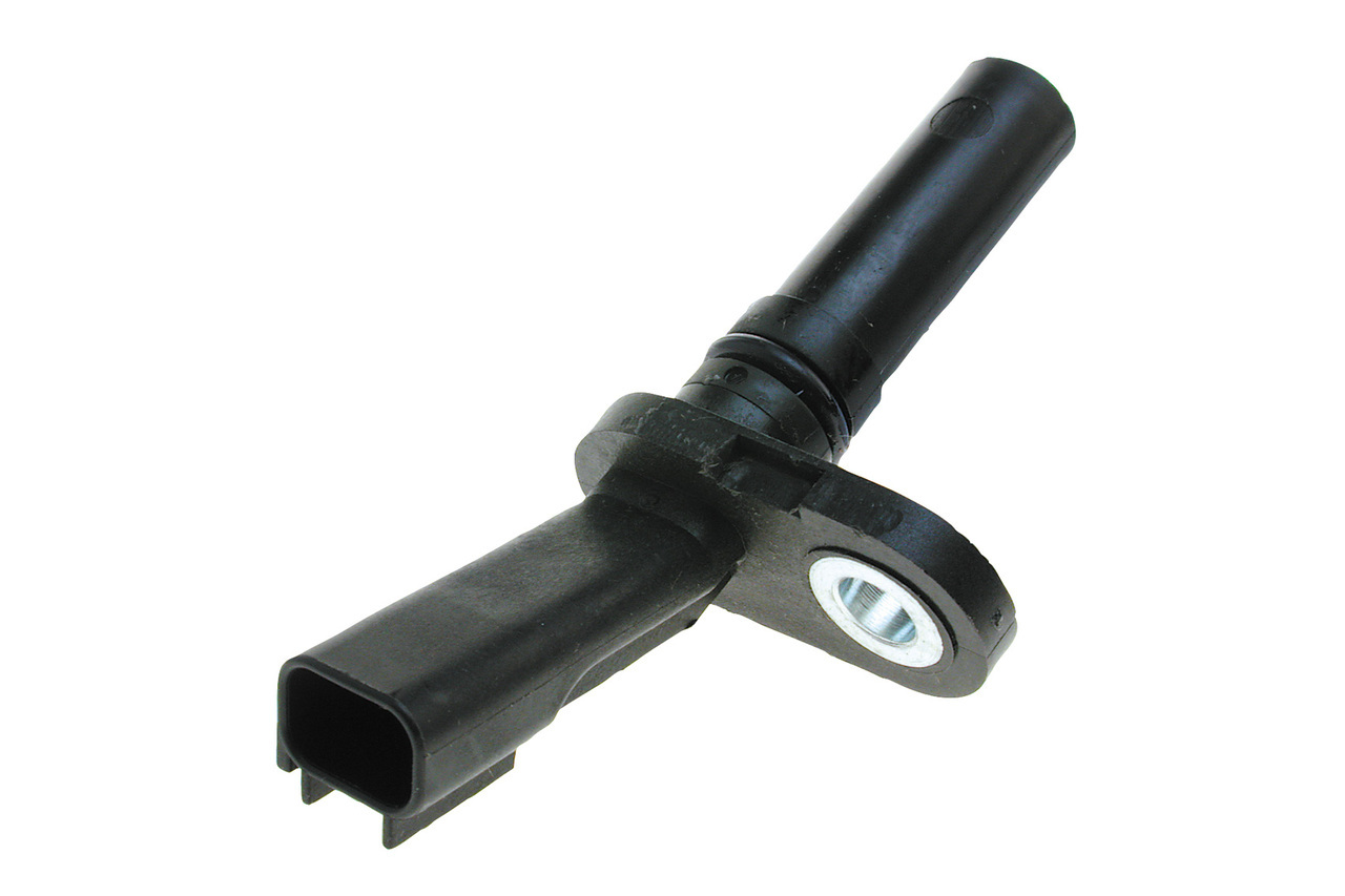 PC320 (Right) EC0169 (Left) | Connector & Pins |
| Ignition Coil | 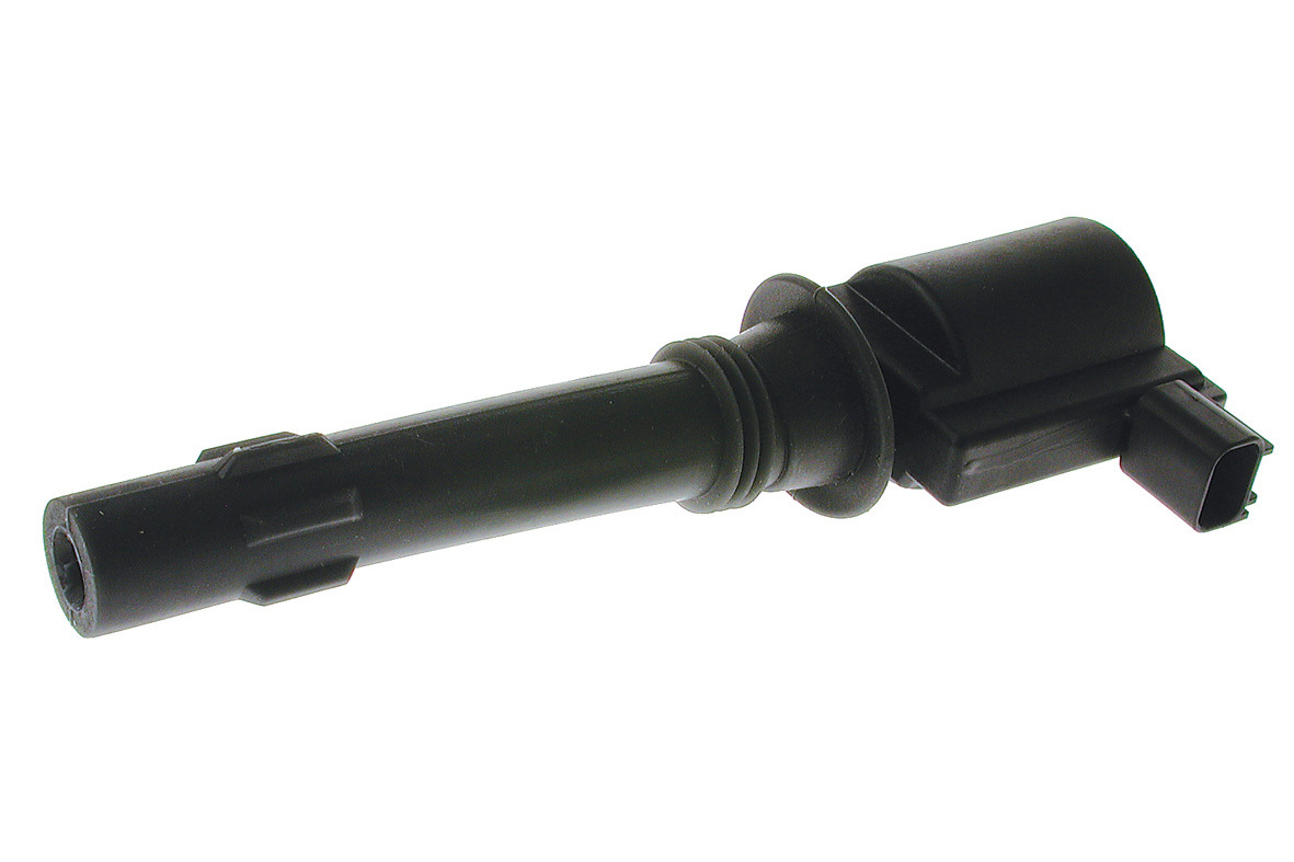 IGC-163M A2C59513771 (Continental) – suit BA BF Falcon IGC-314M A2C59515429 (Continental) – suit FG FGX Falcon | Connector & Pins – suit IGC-163M Connector & Pins – suit IGC-314M |
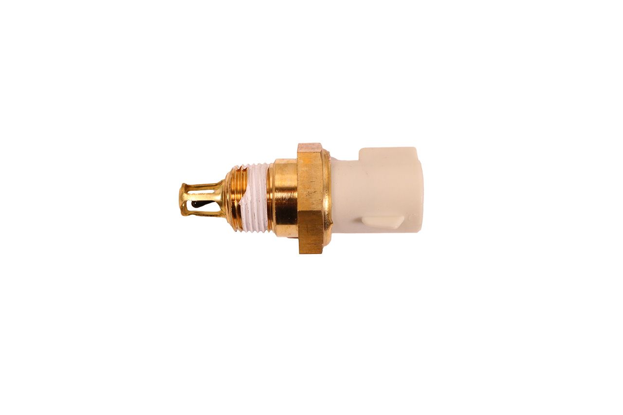
| Coolant Temperature Sensor | 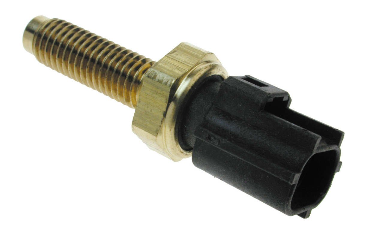 KW-1349 – suit AU BA BF Falcon 33746 – suit FG Falcon | 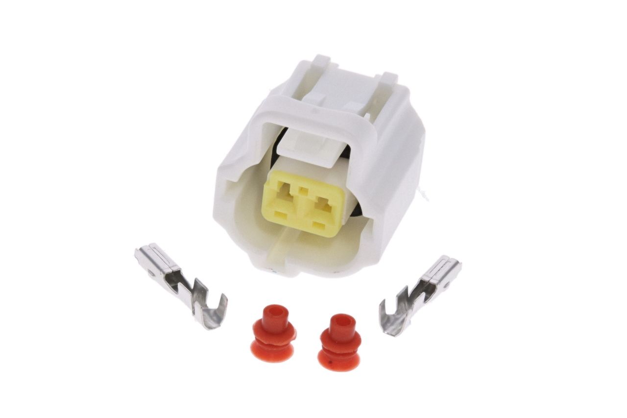 Connector & Pins | Pigtail |
| VCT Cam Actuator | 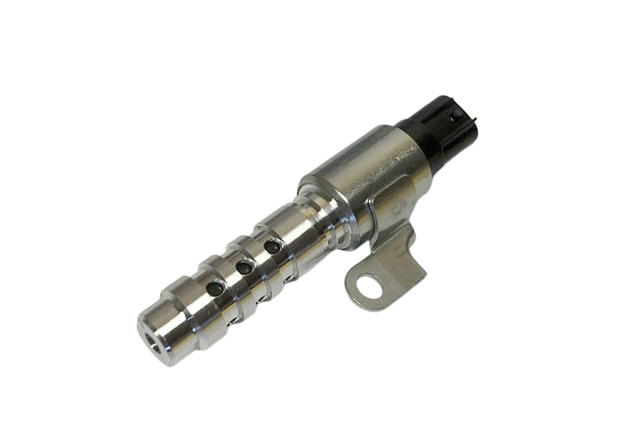 VCA-001 – suit Late BA BF FG Falcon VCA-002 – Early BA Falcon | 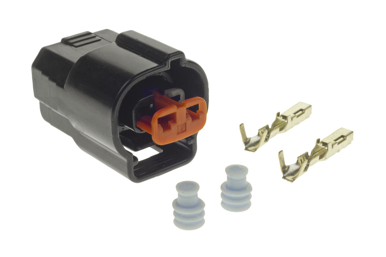 Connector & Pins | Pigtail |
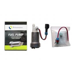
| Fuel Pump Module | 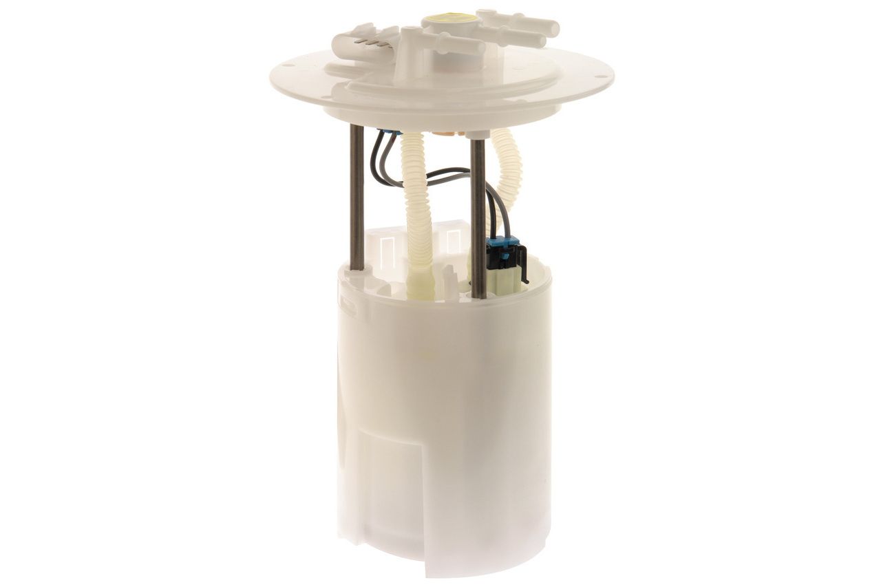 EFP-125M (Icon) EFP-125 (Delphi) – suit BA BF Falcon (Turbo Sedan) EFP-272M – suit FG Falcon (Turbo Sedan) EFP-123M (Icon) EFP-123 (Delphi) – suit BA BF Falcon (Wagon) EFP-126M – suit BA BF Falcon (Ute) EFP-269M – suit FG Falcon (Ute) |  Connector & Pins – suits all Barra Fuel Pump Modules Pigtail – internal connector for Fuel Pump TC6443 – pump adapter to Walbro 460 TC7437 – internal connector to MRA (Sedan) |
| Fuel Pump | 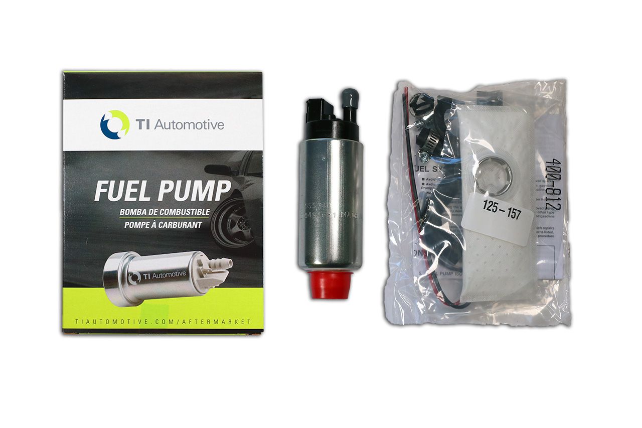 GSS340 – suit BA BF Falcon |  Connector & Pins |
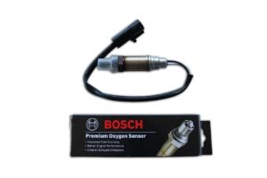
| Oxygen O2 Sensor | 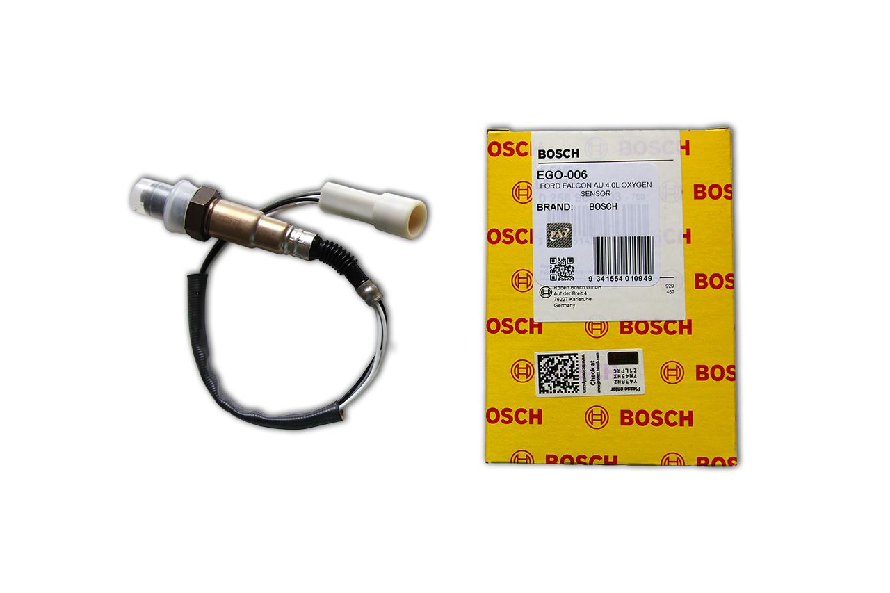 Bosch 0 258 986 603 – suit BA BF FG FGX & AU Falcon | 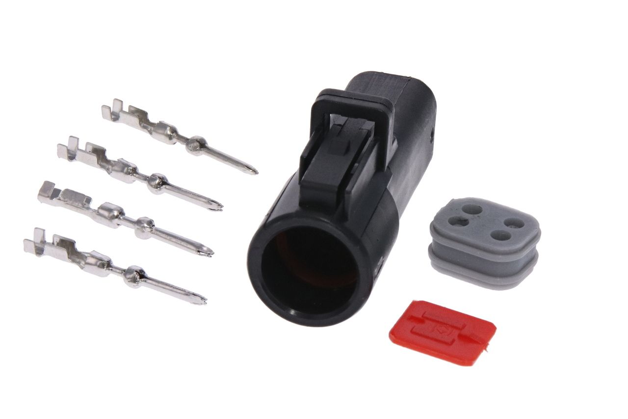 Connector & Pins | Pigtail |
| BA BF Throttle Position Sensor | 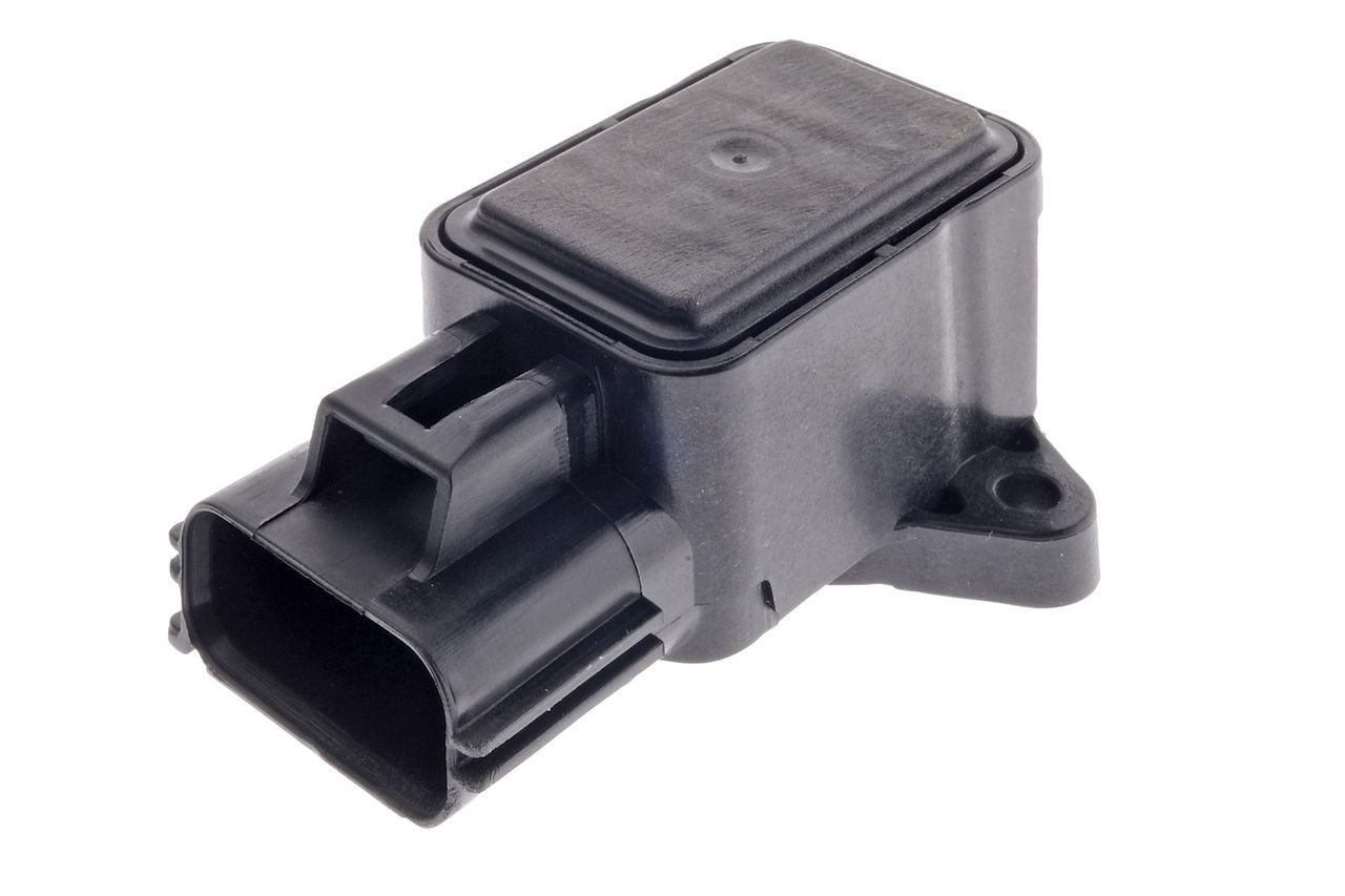 TPS-062 | Connector & Pins |
| BA BF DBW Throttle Body | 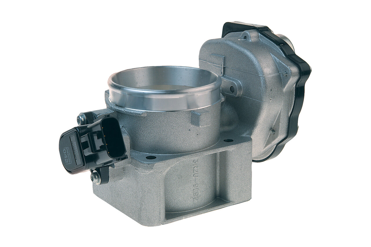 TC8581 Includes TPS & Actuator Motor | 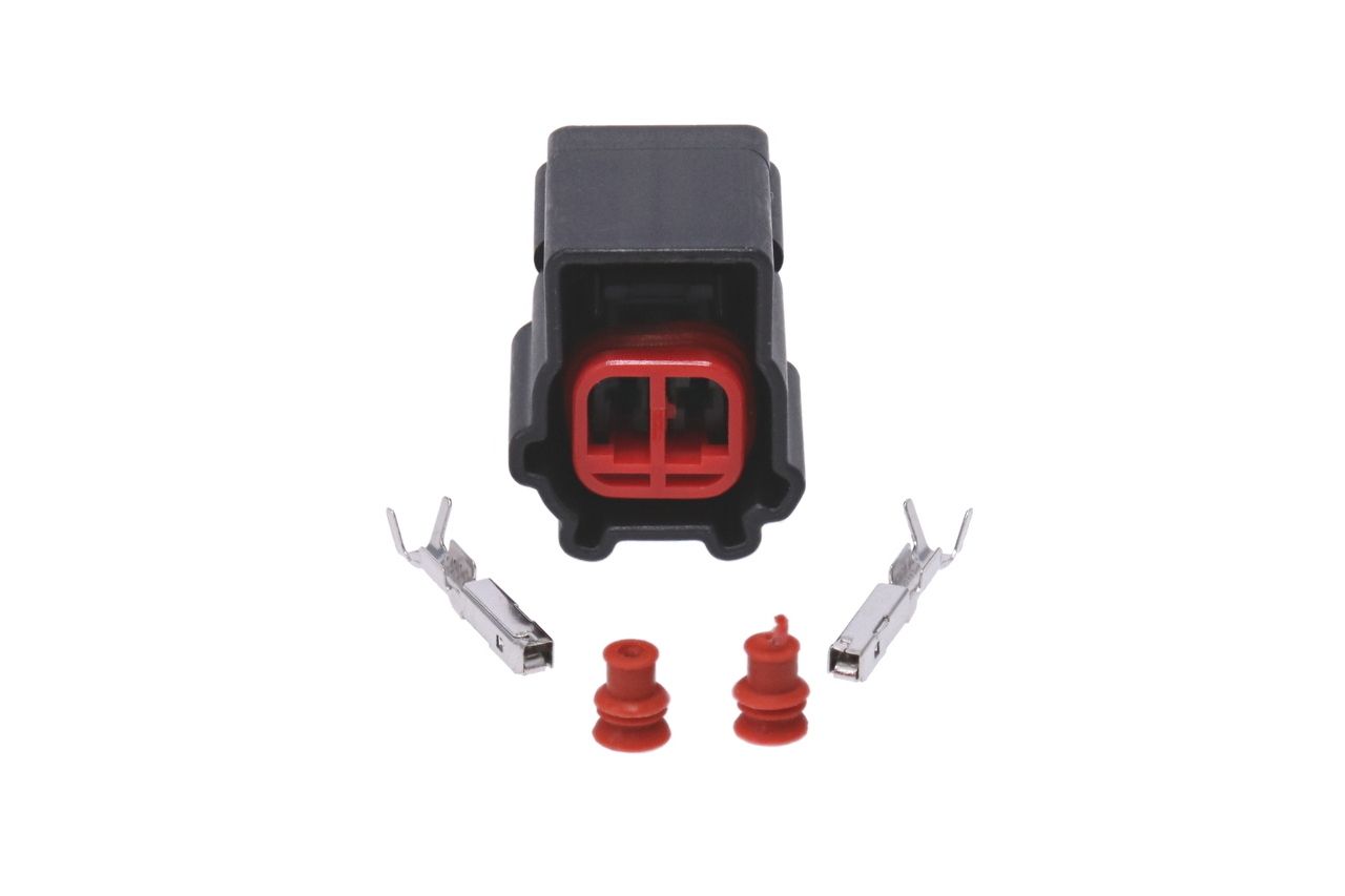 Connector & Pins |
| FG DBW Throttle Body | COMING SOON | 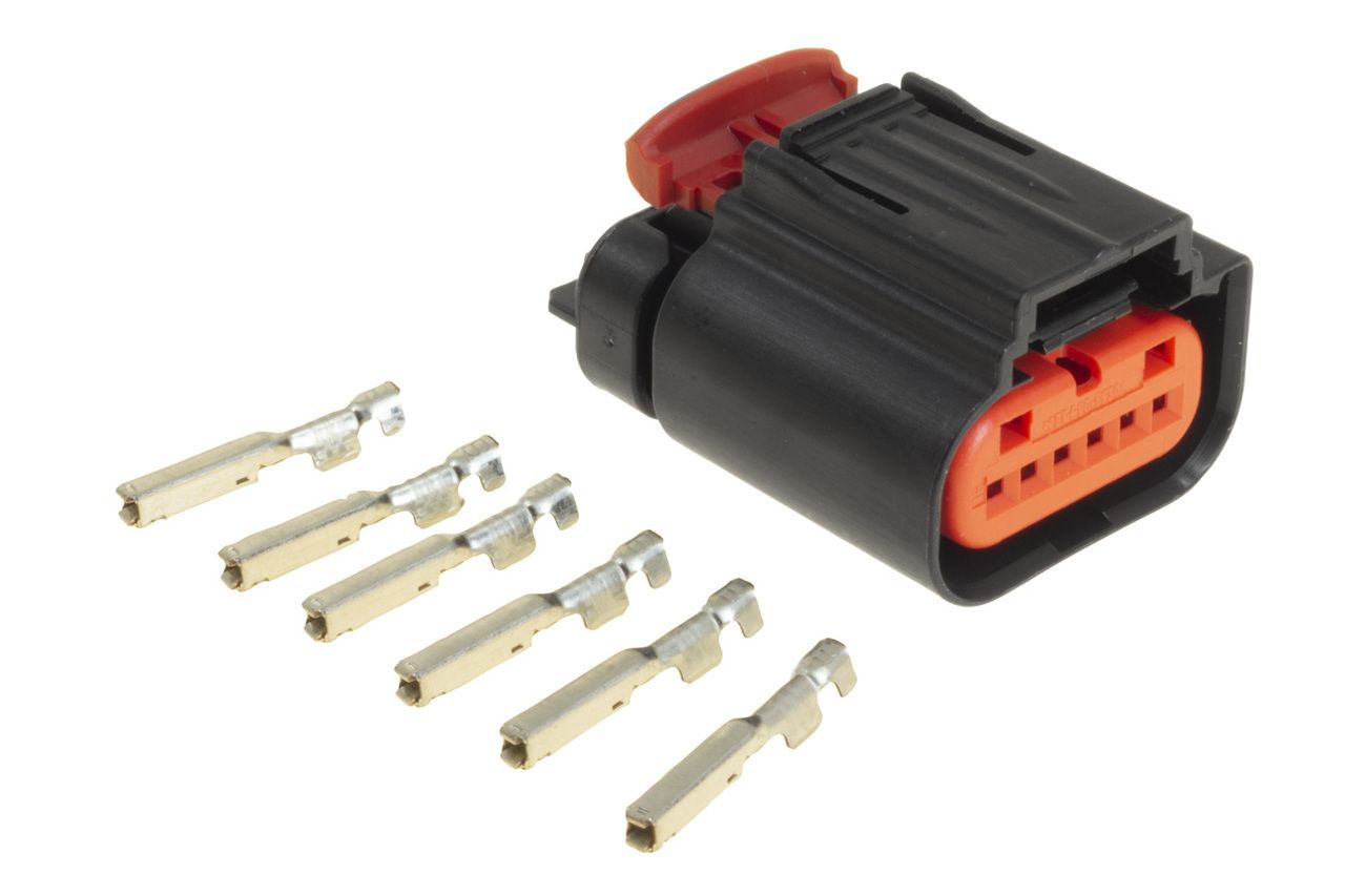 Connector & Pin |
| AC Compressor | COMING SOON | 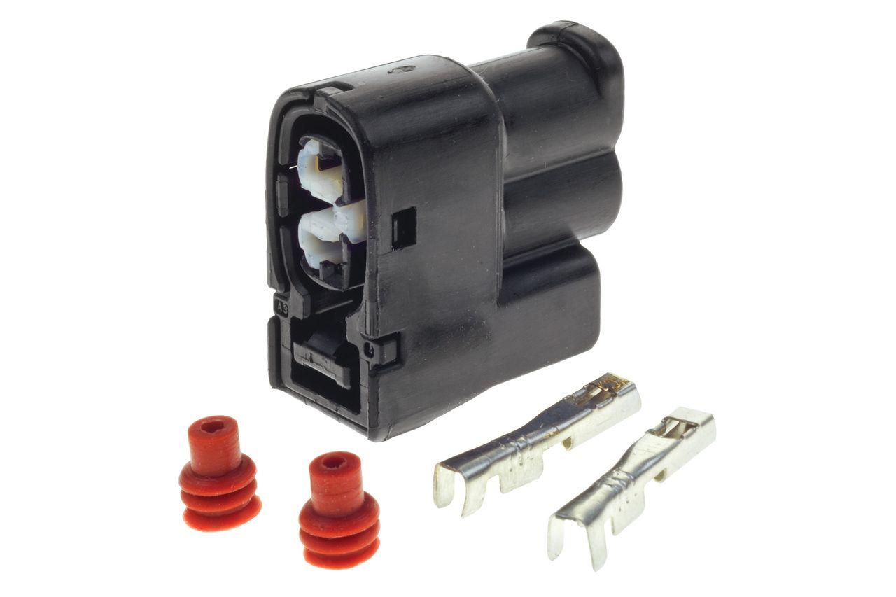 Connector & Pins |
| AC Pressure Sensor (BA BF FG Mk1) | COMING SOON | 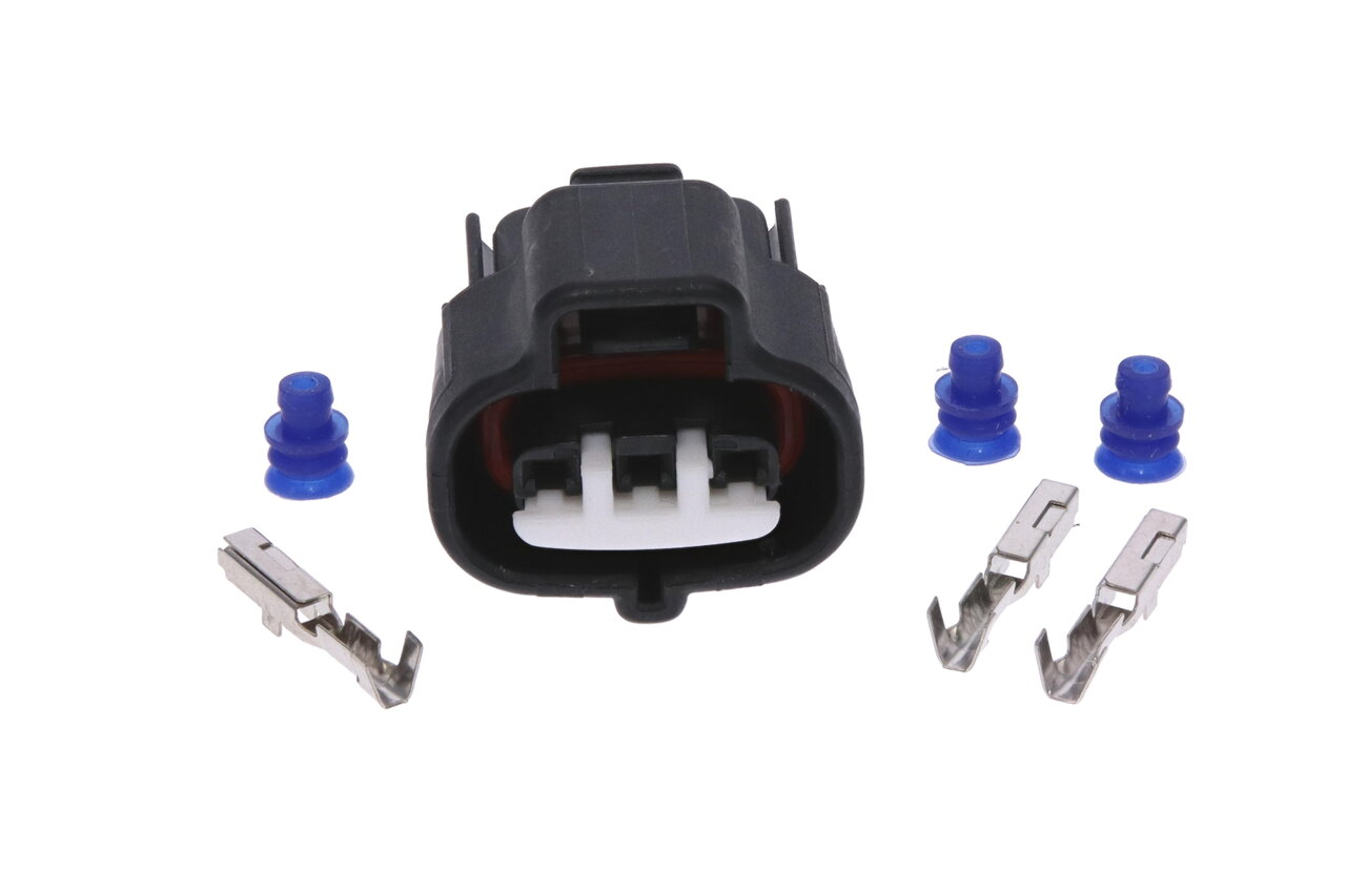 Connector & Pins |
| AC Pressure Sensor (FG Mk2 FG X) | COMING SOON | COMING SOON |
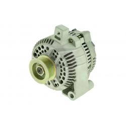
| 3 Pin Alternator | 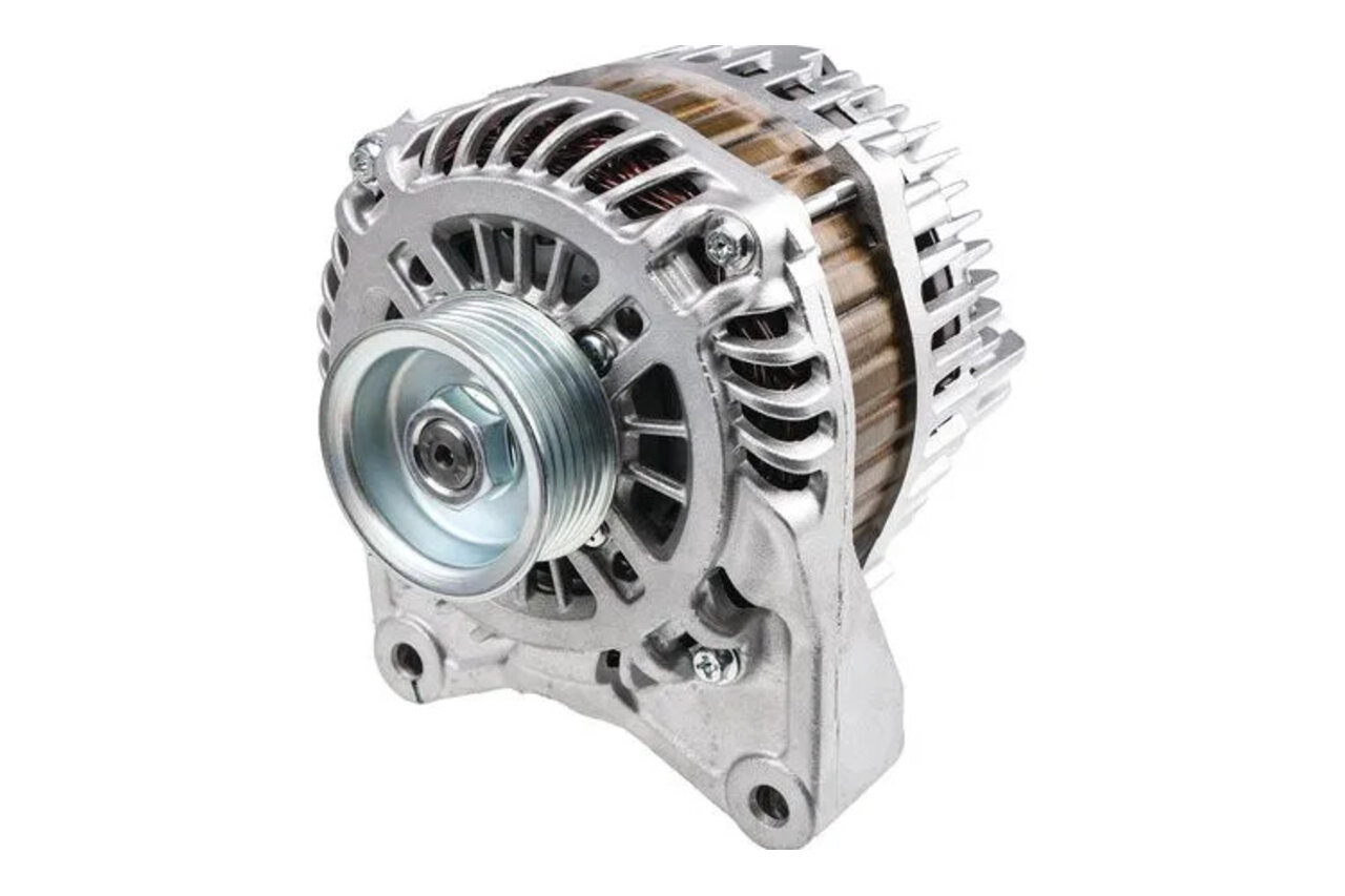 65-6358 – suit BF FG Falcon | 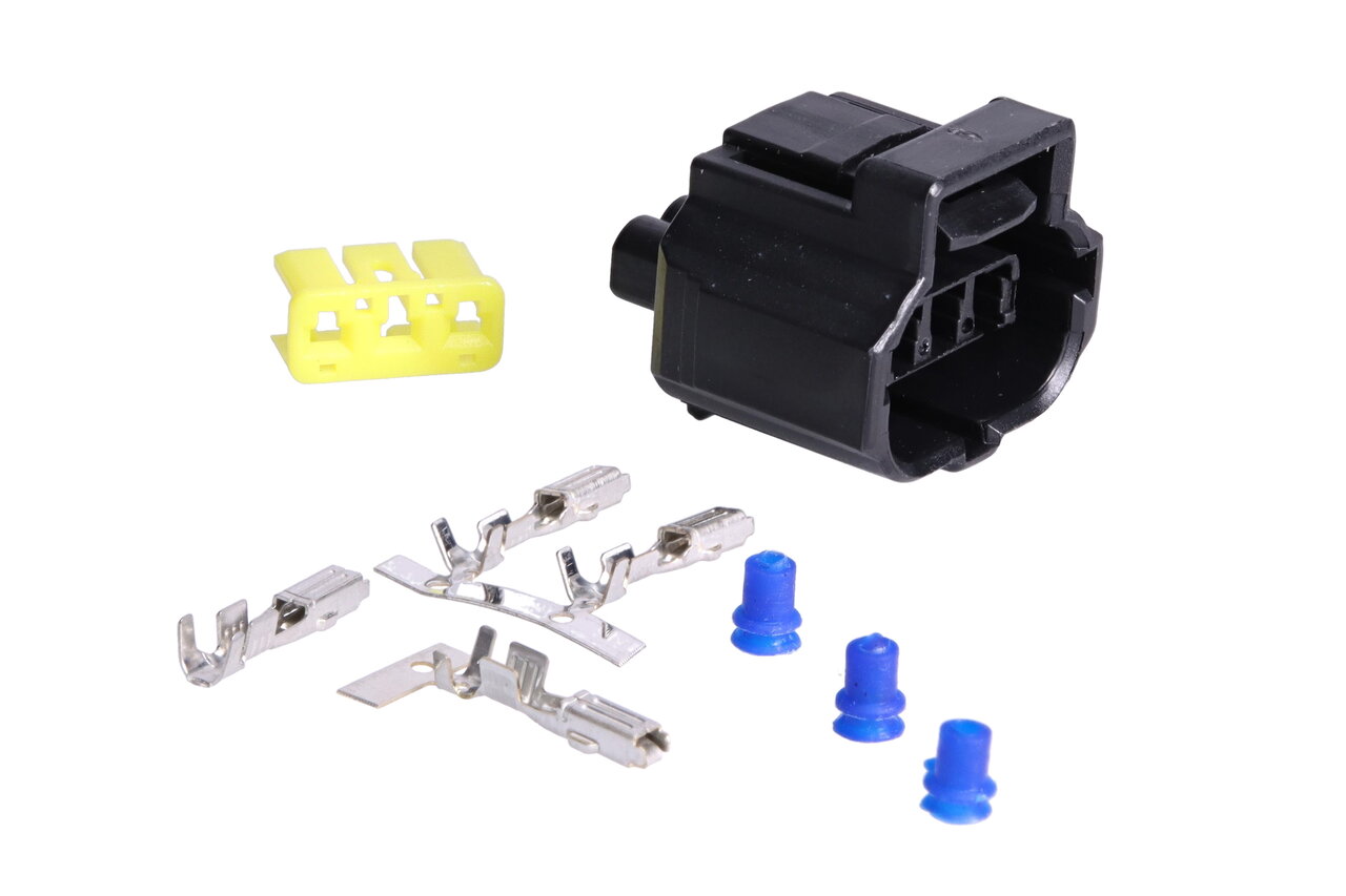 Connector & Pins |
| 2 Pin Alternator | 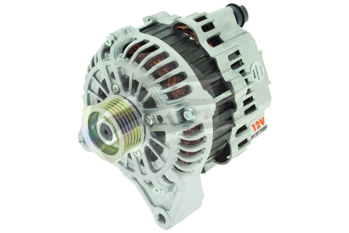 65-6347 – suit BA Falcon | 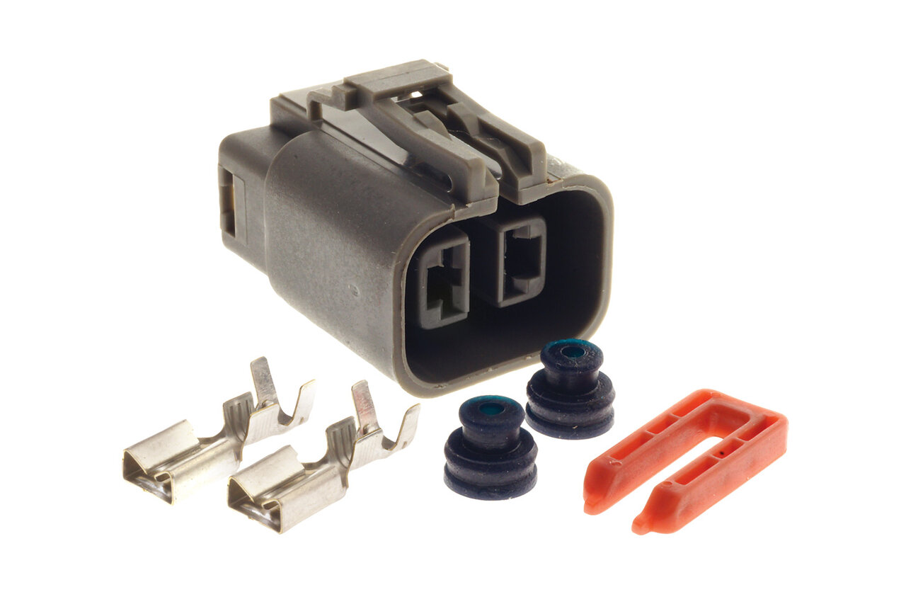 Connector & Pins |
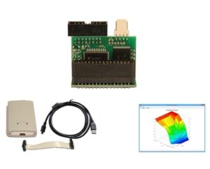
| OBD2 Plug | 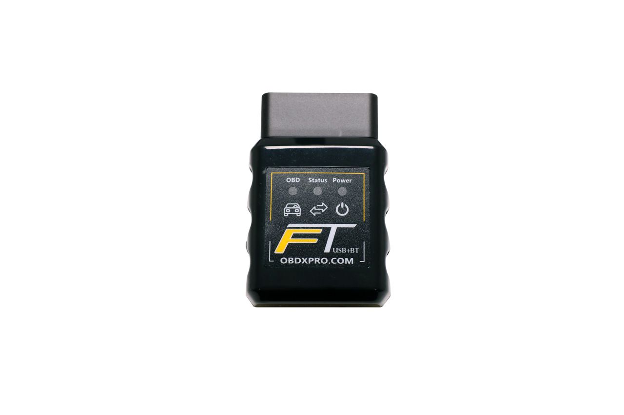 Basic Scan Tool – VGate VLinker FS BT J2534 Programming Cable – OBDX FT | 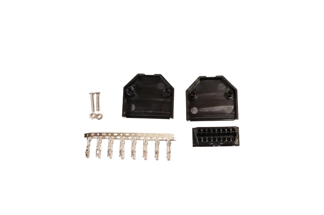 Connector & Pins |
| ZF 6HP Connector | N/A | 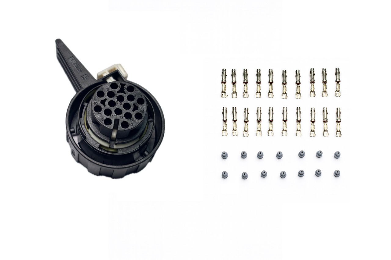 ZF 6HP19 / 6HP21 / 6HP26 / 6HP28 / 6HP32 |
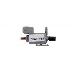
| Boost Control Solenoid | 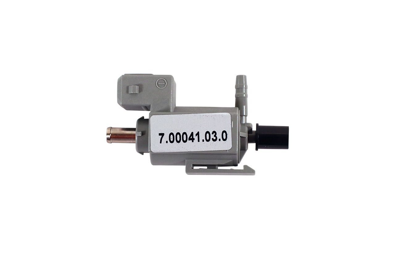 7.00041.03.0 | Connector & Pins | Pigtail |
| Relays | 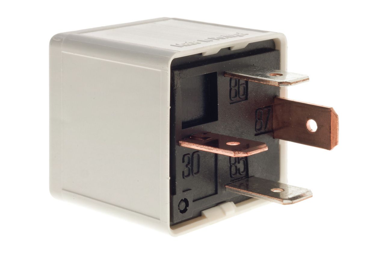 1393303-3 – suit BA BF FG Falcon (accessory, headlights, ignition, thermo fan 1 & 3, power windows, starter, demister) RY116 – suit BA BF FG Falcon (A/C, corner lamp, ECU, fuel pump, horn, tail lights, fog lights) 1-1414731-0 -suit BA BF FG Falcon (thermofan 2) | 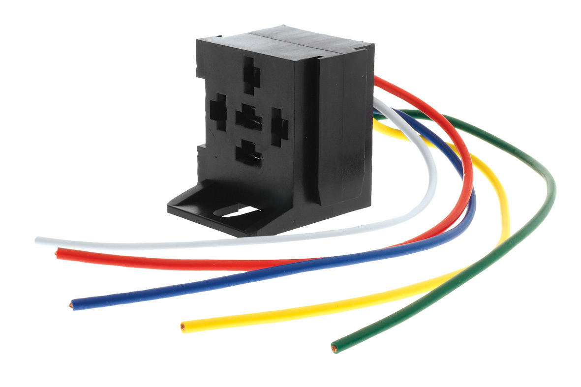 Connector & Pins – suit 1393303-3 & RY116 |
If you have any feedback on this guide or can help us identify any missing connectors or parts let us know and we’ll add them!
Thanks to Jamie C and Mackielec for helping to start off this list.


