EA-EL Ford Falcon EEC-V and EEC-IV ECUs may predate the use of OBD2 diagnostic code readers, but they still have advanced diagnostic modes that provide codes to identify engine sensor and wiring problems. This guide outlines how to read stored diagnostic codes on the Ford EEC (sometimes called OBD1) to help with finding problems, and explains how to get into timing mode to set the base timing correctly.
General
There are a number of diagnostic terms, features and modes in EA-EL Falcons. At a high level:
- Diagnostic Connector – This is where you access the terminals for the diagnostic modes of the ECU, ABS, and TCM. This guide only covers the ECU. The connector is located above the fuse box on EBII-EL Falcons, and to the left of the brake booster in EA Falcons. There are also diagnostic modes in the Climate Control Module.
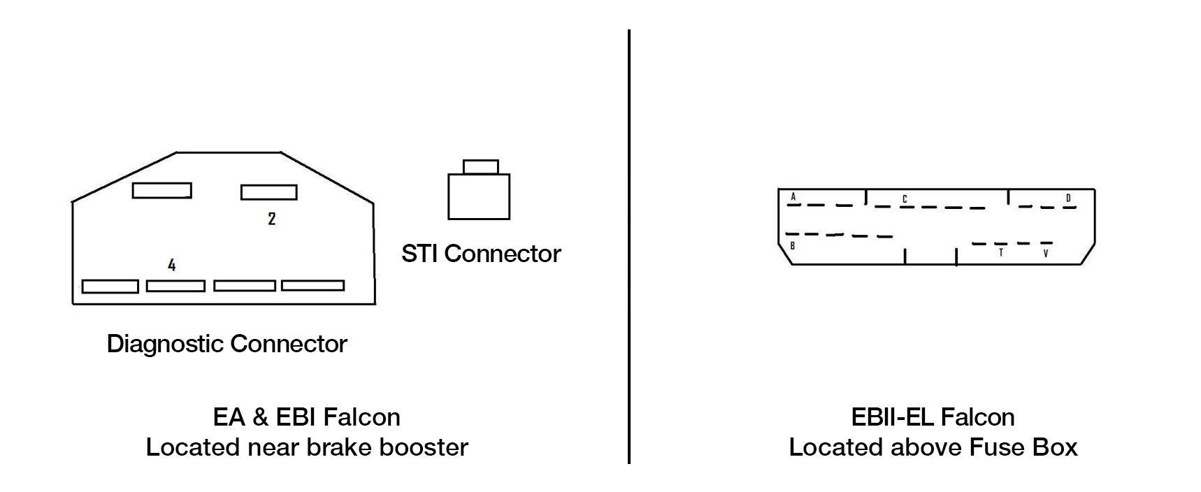
Location and pinout of diagnostic connectors for EA-EL Ford Falcon
- EEC Diagnostic Modes – There are a number of diagnostic modes in the ECU. These include – Key On Engine Off (KOEO), Key On Engine Running (KOER), Fan Test (EF/EL Only), Balance Test (V8 only), and Wiggle Test. This guide only covers the KOEO test which is most helpful for reading stored codes.
- STI/STO – The Self Test Input (STI) and Self Test Output (STO) pins are used to enter diagnostic mode and read the output codes respectively. The STI is the single pin connector on the EA, or the top left pin on the EBII-EL. The STO is pin 4 of the 6 pin diagnostic connector the EA, or the 5th pin on the EBII-EL connector.
Reading Codes in KOEO Diagnostic Mode
This guide will focus on the Key On Engine Off (KOEO) diagnostic mode, which provides the most useful info. To run the KOEO test:
- With the Ignition Switch Off, connect the Engine STI Input on the diagnostic connector to ground. The STI Input is the first pin on the top left of the connector on the EBII-EL. Connect this to the ground pin directly below it.
- Connect an LED, Analog Multimeter, or Buzzer between the STO Pin and Ground. The STO Pin is the 5th Pin from the left on the upper row on the EBII-EL.
- Turn the Ignition Switch to On, but do not start the engine
- Write down the codes on a piece of paper, which will be displayed as flashes of the light/buzzer/meter in the following sequence:
- On Demand Codes – Hard Faults
- Separator Code – Numeral 10
- Memory Codes – Intermittent Faults
 Don’t want to mess around with test lights? Our Diagnostic Code Reader tool plugs directly into the factory diagnostic plug and allows reading and resetting codes in the ECU, Transmission, Airbag and ABS modules on its bright LED display in all XF, EA, EB, ED, EF and EL Falcons (including Ute, Fairlane and XR6)!
Getting into KOER Diagnostic / Base Timing mode
Base timing is set after the Key On Engine Running (KOER) diagnostic tests are completed. These take 1-2mins as above. The steps to get into this mode are as follows:
- Start the engine.
- Connect an LED, Analog Multimeter, or Buzzer between the STO Pin and Ground. The STO Pin is the 5th Pin from the left on the upper row on the EBII-EL.
- With the engine running, connect the Engine STI Input on the diagnostic connector to ground. The STI Input is the first pin on the top left of the connector on the EBII-EL. Connect this to the ground pin directly below it. The engine idle will increase when the ECU enters KOER mode.
- Write down the codes on a piece of paper, which will be displayed as flashes of the light/buzzer/meter in the following sequence:
- On Demand Codes – Hard Faults
- Separator Code – Numeral 10
- Memory Codes – Intermittent Faults
- After the KOER test completes flashing codes (approx 1-2 mins), the idle will drop as the engine drops to fixed base timing. You have approx 1-2min to adjust the timing.
- Rotate distributor to adjust. EA-ED 6 cylinder should be 10 deg BTDC. EL 6 cylinder should be on the IGN mark. All 5.0L V8s should be 30 deg BTDC.
- The code information is at the end of this article.
Thermofan Diagnostics
Credit to Fordmods for this section.
There are 2 methods to diagnose problems with the thermo fan system on EF and EL Model Falcons.
Testing the Thermo Fan operation – Easy method
- Ensure that it is safe to start the engine on the vehicle to be tested. (I.E. no tools in engine bay, etc).
- Start the engine of the vehicle.
- For non climate control cars – Turn the Air-conditioning to MAX, and the Fan speed to MAX.
- For auto climate control cars – Press AUTO, and set the temperature to the lowest possible setting.Once this has been carried out, the Thermo fans should be running at their High Speed setting.
Testing the Thermo Fan operation – Using the EEC Diagnostic mode
- With the Ignition Switch Off, Connect the Engine STI Input to ground, (The STI Input is the First pin from the left, upper row, connect this to the Pin directly below it)
- Place the Transmission in to gear to turn the Thermo Fans On, and Place the Transmission into neutral to stop Fan operation.If both fans do not operate, then you may have trouble codes logged within the EEC-V memory. You must clear these codes for the Thermo fan test to work!
EEC-IV Diagnostic Codes
| EEC-IV Diagnostic Codes | |||||||
| Code | Description | ||||||
|---|---|---|---|---|---|---|---|
| 10 | Separator Code | ||||||
| 11 | System Pass | ||||||
| 12 | High RPM Idle Check Fail | ||||||
| 13 | Low RPM Idle Check Fail | ||||||
| 14 | Unsteady PIP Signal during Idle Test | ||||||
| 15 | Bad ROM / KAM Data | ||||||
| 16 | RPM Too Low to run Fuel Test | ||||||
| 19 | Internal EEC-IV Power too Low | ||||||
| 21 | ECT Circuit | ||||||
| 22 | MAP Sensor Circuit | ||||||
| 23 | TPS Sensor Out Of Range | ||||||
| 24 | ACT Sensor Circuit | ||||||
| 26 | Trans Oil Temp Sensor Out Of Range | ||||||
| 27 | Shift Lever Position Input Fault | ||||||
| 36 | Shaft Speed Signal Fault (speedo sensor) | ||||||
| 41 | Oxygen Sensor always Lean | ||||||
| 42 | Oxygen Sensor always Rich | ||||||
| 44 | Smartlock Enable Code not present | ||||||
| 51 | Engine Coolant Temperature Voltage too High | ||||||
| 52 | Power Steering Switch Open (Ignore on Utes & Vans) | ||||||
| 53 | Throttle Position Sensor Voltage too High | ||||||
| 54 | ACT Voltage too High | ||||||
| 57 | Power / Economy Switch Circuit | ||||||
| 61 | Engine Coolant Temperature Voltage too Low | ||||||
| 63 | Throttle Position Sensor Voltage too Low | ||||||
| 64 | ACT Voltage too Low | ||||||
| 67 | Air Conditioning Input Fault | ||||||
| 72 | No Dynamic MAP Change | ||||||
| 73 | No Dynamic TPS Change | ||||||
| 77 | Goose Test NOT Performed | ||||||
| 78 | Transmission Battery Circuit | ||||||
| 85 | Canister Purge Solenoid Output Check Fail | ||||||
| 87 | Fuel Pump Output Circuit Fail | ||||||
| 95 | Solenoid 5 Fault (variable pressure control) | ||||||
| 96 | PCS Solenoid Fault (pressure control) | ||||||
| 98 | ON/OFF Solenoid Fault Circuit | ||||||
| 99 | Throttle Not Learnt | ||||||
More diagnostic code descriptions available here.
EEC-V Diagnostic Codes
| EEC-V Diagnostic Codes | |||||||
| Code | NAME | Description | I6 | V8 | KOEO | ER | CONT |
|---|---|---|---|---|---|---|---|
| 111 | Pass | There are no codes to display for the selected test | X | X | |||
| 112 | IAT Shorted to ground | The IAT Value is too low. Can be caused by short to ground, or faulty sensor | X | X | X | X | |
| 113 | IAT Shorted to B+ or Vref | The IAT Value is too high. Can be caused by shorts to Vref, B+ or faulty sensor | X | X | X | X | |
| 114 | IAT Sensor out of Calibration | The IAT Voltage is out of the normal range. Can be caused by the sensor going out of spec | X | X | X | X | |
| 116 | ECT Sensor out of calibration | The ECT Value is out of range or is erratic | X | X | X | X | |
| 117 | ECT Shorted to Ground | The ECT Value is too low. Can be caused by a short to ground, or faulty sensor | X | X | X | X | |
| 118 | ECT shorted to B+ or Vref | The ECT Value is too high. Can be caused by a short to B+, Vref, or faulty sensor | X | X | X | X | |
| 121 | TP Sensor out of range | Throttle position sensor is out of range. Can be caused by the sensor going out of spec | X | X | X | X | |
| 122 | TP Sensor shorted to ground | The Value for the Throttle position sensor is too low. Can be caused by a short to ground, or faulty sensor | X | X | X | X | |
| 123 | TP Sensor shorted to B+ or Vref | The Value for the Throttle position sensor is too high. Can be caused by a short to V+, Href, or faulty sensor | X | X | X | X | |
| 126 | MAP Sensor out of calibration | The MAP sensor is producing a frequency that is outside the normal range, or no frequency at all | X | X | X | X | |
| 129 | NO MAP/MAF change in goose | EEC did not see the MAP(I6) or MAF(V8) value change when the engine was goosed in the ER test | X | X | X | ||
| 157 | MAF shorted to ground | The MAF voltage is too low. Can be caused by short to ground or faulty sensor | X | X | |||
| 158 | MAF shorted to B+ or Vref | The MAF voltage is too high. Can be caused by shorts to Battery, or Vref or faulty sensor | X | X | X | ||
| 159 | MAF sensor out of calibration | The MAF Voltage is out of the normal range. Can be caused by sensor going out of spec | X | X | X | ||
| 167 | No Throttle Position Change in Goose | EEC did not see the throttle position sensor change when the engine was goosed in ER test | X | X | X | ||
| 172 | System always lean HO2S(1) | The engine is always running lean (V8) | X | X | X | V8 | |
| 173 | System always rich HO2S | The engine is always running rich. Can be caused by a faulty sensor, cold engine, MAP hose off, or fuel system (V8) | X | X | X | V8 | |
| 176 | System always lean HO2S(2) | The engine is always running lean (V8) Can be caused by a faulty sensor, cold sensor, or exhaust manifold leak | X | X | X | ||
| 177 | System always rich HO2S(2) | The engine is always running rich. Can be caused by a faulty sensor, cold engine, MAP hose off, or fuel system | X | X | X | ||
| 211 | PIP Erratic during Idle test | The rate of change of the PIP signal is out of range (IE EEC saw an accell or decel that was too fast) could be caused by CKP sensor or an internal IDIS failure | X | X | X | ||
| 214 | CMP Sensor Input failed | The signal from the CMP sensor has gone out of normal range. Could be caused by a faulty CMP sensor or wiring | X | X | |||
| 215 | EDIS Coil A Failed | Coil A failed to fire. Could be caused by a faulty coil or wiring | X | X | |||
| 216 | EDIS Coil B Failed | Coil B failed to fire. Could be caused by a faulty coil or wiring | X | X | |||
| 217 | EDIS Coil C Failed | Coil C failed to fire. Could be caused by a faulty coil or wiring | X | X | |||
| 226 | Unknown EDIS Coil Failure | Associated with code 214 – CMP Failure. One ohm the EDIS coils failed to fire, and because the CMP signal also failed, EEC was not able to determine which coil | X | X | |||
| 227 | Knock Sensor Failure | The knock sensor failed to provide a signal while the engine was within the normal knock sensor operating conditions (I.E. >50% load <4500 RPM) NOTE : knock sensor codes may result when running on Non-Factory fitted LPG systems | X | X | |||
| 232 | EDIS CPU Failed | Internal EEC Fault – the EDIS CPU has failed | X | X | |||
| 327 | EGR Shorted to ground | The EGR Voltage is too low. Can be caused by a short to ground or a faulty sensor | X | X | X | ||
| 328 | EGR Valve position too low | The EGR Valve position is Low. Can be caused by a closed valve | X | X | X | ||
| 332 | EGR Valve not working | EGR valve position does not change during ER test. Can be caused by a vacuum leak in the EGR control system | X | X | X | ||
| 334 | EGR Valve position too high | The EGR position is out of its normal range. Can be caused by a Fully open Valve | X | X | X | ||
| 335 | EGR Sensor out of calibration | The EGR voltage is out of the normal range. Can be caused by the sensor going out of spec. | X | X | X | ||
| 411 | ISC Low Idle fail | The Idle Speed Controller was not able to control the low idle speed during the engine running test | X | X | X | ||
| 412 | ISC High Idle fail | The Idle Speed Controller was not able to control the High idle speed during the engine running test | X | X | X | ||
| 452 | Speedo Signal Fault | The Speedo signal is intermittent or non existent | X | X | X | ||
| 511 | Internal EEC V Fault | The EEC Module is Faulty – Replace | X | X | X | X | |
| 512 | Internal EEC Fault | Faulty EEC Module | X | X | X | ||
| 513 | Battery Voltage Too Low | The Internal battery power voltage is too low. Can be caused by a low system voltage, or internal EEC fault | X | X | X | ||
| 521 | PSP Failed open | The switch must be closed for the KOEO and ER test. During ER test, the steering must be turned approx 1/2 turn. Can be caused by disconnected or faulty switch, or failure to turn steering during test | X | X | X | ||
| 522 | NDS – A/C On | For KOEO test, the transmission must be in either Park, or Neutral, the A/C must also be turned off | X | X | X | ||
| 523 | AC Blower Fan Sensor fault | EEC cannot see a signal from the A/C blower fan. Can be caused by open circuit, blown fuse (Hi Series), or short to +12V (Low Series) | X | X | |||
| 524 | LPG Enabled | LPG option is selected This does not indicate any system fault | X | X | |||
| 538 | Operator did not goose | ER test requires that the operator briefly open the throttle fully | X | X | X | ||
| 578 | Battery Voltage too low | The Internal reference voltage is too low for proper transmission operation. Can be caused by a low system voltage or internal EEC fault | X | X | |||
| 628 | Trans Mode Switch Fault | The mode selector (Normal/Econ) signal is operating intermittently. Can be caused by faulty switch or wiring | X | X | X | ||
| 634 | Gear Selector Sensor Faulty | The signal from the Gear Selector switch is too high, too low, or at a value between any 2 normal modes | X | X | X | ||
| 636 | Trans Oil Temp Fault | The transmission oil temperature signal is incorrect. Can be caused by an open circuit, or short to Ground / Batt | X | X | X | ||
| 637 | Trans Temp Link Stuck high | The information Link between the EEC and the 97LE module is at or near +12V. Can be caused by a short to Battery Voltage, or a fault in either of the 2 modules | X | X | |||
| 691 | Trans Solenoid 1 Fault | EEC Cannot control the solenoid. Can be caused by open circuit, or short circuit to Ground, +12V | X | X | |||
| 692 | Trans Solenoid 2 Fault | EEC Cannot control the solenoid. Can be caused by open circuit, or short circuit to Ground, +12V | X | X | |||
| 693 | Trans Solenoid 3 Fault | EEC Cannot control the solenoid. Can be caused by open circuit, or short circuit to Ground, +12V | X | X | |||
| 694 | Trans Solenoid 4 Fault | EEC Cannot control the solenoid. Can be caused by open circuit, or short circuit to Ground, +12V | X | X | |||
| 695 | Trans Solenoid 5 Fault | EEC Cannot control the solenoid. Can be caused by open circuit, or short circuit to Ground, +12V | X | X | |||
| 696 | Trans Solenoid 6 Fault | EEC Cannot control the solenoid. Can be caused by open circuit, or short circuit to Ground, +12V | X | X | |||
| 697 | Trans Solenoid 7 Fault | EEC Cannot control the solenoid. Can be caused by open circuit, or short circuit to Ground, +12V | X | X | |||
| 777 | Drivers side Cooling Fan not operating | The Fan motor is not drawing current from battery when switched on by EEC Module during self test | X | X | X | ||
| 778 | Passenger side Cooling Fan not operating | The Fan motor is not drawing current from battery when switched on by EEC Module during self test | X | X | X | ||
| 783 | Serial Link output check fail | Serial Link is faulty. Can be caused by open circuit, or short to Ground, +12V | X | X | X | ||
| 784 | EGR Output check fail | EGR Output is faulty. Can be caused by open circuit, or shorts to Ground, +12V | X | X | X | ||
| 785 | CANP Output check fail | CANP Output is faulty. Can be caused by open circuit, Ground, or +12V | X | X | X | ||
| 786 | PIL Output check fail | Performance Indicator Light output is faulty. Can be caused by open circuit, or shorted to Ground, +12V | X | X | X | ||
| 787 | Fuel Pump Output Check Fail | Fuel Pump output is faulty. Can be caused by open circuit, or shorted to Ground, +12V | X | X | X | ||
| 788 | ACC Output check fail | A/C Control relay output is faulty. Can be caused by open circuit, or shorted to Ground, +12V | X | X | X | ||
| 789 | RCO Output check fail | Recirculation override Output is faulty. Can be caused by open circuit, or shorted to Ground, +12V | X | X | X | ||
| 791 | FC1 Output Check Fail | Electro Drive fan 1 output is faulty. Can be caused by open circuit, or shorted to Ground, +12V | X | X | X | ||
| 792 | FC2 Output Check Fail | Electro Drive fan 2 output is faulty. Can be caused by open circuit, or shorted to Ground, +12V | X | X | X | ||
| 793 | FC3 Output Check Fail | Electro Drive fan 3 output is faulty. Can be caused by open circuit, or shorted to Ground, +12V | X | X | X | ||
| 794 | FC4 Output Check Fail | Electro Drive fan 4 output is faulty. Can be caused by open circuit, or shorted to Ground, +12V | X | X | X | ||
| 795 | BBM Output Check Fail | Broad Band Manifold output is faulty. Can be caused by open circuit, or shorted to Ground, +12V | X | X | |||
| 837 | Evaporator Sensor shorted to ground | The evaporator temperature voltage is too low. Can be caused by a short to ground or faulty sensor | X | X | X | X | |
| 838 | Evaporator Sensor shorted to B+ or Vref | The evaporator temperature voltage is too high. Can be caused by a short to +12V or faulty sensor | X | X | X | X | |
| 839 | Evaporator Sensor out of calibration | The evaporator temperature voltage is out of the normal range. Can be caused by the sensor going out of spec | X | X | X | ||
| 844 | Vehicle Immobilised | EEC is not receiving the enable code from the BEM. Can be caused by open circuit, short to +12V, or an immobilisation (BEM) problem | X | X | X | ||
| 845 | Vehicle Immobilised – Plant Mode | Immobilisation system is still in plant mode. BEM must be trained to the electronic lock assembly | X | X | X | ||
| 998 | ER Test Error | In the ER test, one or more of the major sensors (IAT, ECT, MAP, TP) are faulty. Run KOER test to determine the cause of the error | X | X | |||
For more information see the guide at Fordmods or this guide from Snapon.