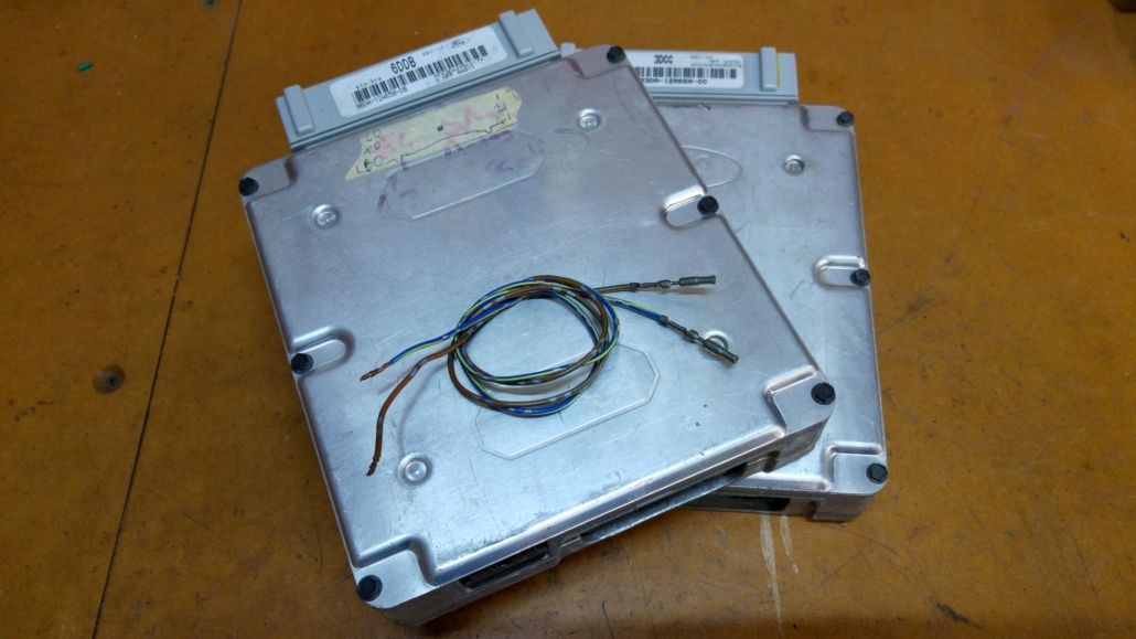
Fitting an EL ECU to an EA-ED Falcon
This guide outlines the steps involved in fitting an EL ECU into an EA, EB, ED, NA, NC, or XG Falcon/Fairmont/Fairlane 6 cylinder. This provides several benefits, including:
- Faster ECU with larger memory capacity and more advanced strategy programming
- Better idle control
- Better spark control
- Better automatic transmission control including more advanced shifting
- EF/EL Broadband Manifold (BBM) control
- Thermofan control
- More current definitions
Fitting an EL ECU into Pre-Smartlock EA-EB requires the use of a Stage 1 J3 chip to disable the Smartlock function in the ECU. Contact us for more information.
Fitting the EL ECU
Parts required:
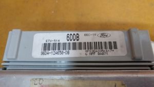
- EL ECU
- Phillips head screwdriver
- 10mm Socket
- Spare ECU connector terminals (if adding BBM or thermofan control)
- Remove the passenger side kick panel and unscrew the bracket holding the ECU in. Then, using a 10mm socket, loosen the connector and remove the old ECU from the car.
- If you plan on fitting a J3 Chip, see our J3 Chip Installation Instructions and prepare the ECU while you are here.
- Plug in the new ECU by tightening the 10mm bolt on the top of the connector.
- Start the vehicle to test the ECU is working correctly. If the fuel pump runs constantly when the ignition is in ON, the ECU is faulty and should be replaced. If the vehicle cranks but does not start, your car may be pre-Smartlock, and require a J3 Chip to remove it. Contact us for more info.
- Use the factory retaining bracket to secure the ECU back into the vehicle, and refit the kick panel.
- Start the engine and get to operating temperature.
- Reset the base timing to EL spec (0 degrees advance).
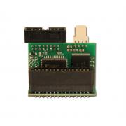
J3 Chip Options
To get the most from your EL ECU, we can program a J3 chip to suit any modifications made to your engine or driveline, including fuel system, transmission, camshafts, boost etc. See our range of J3 Chips below.
 Stage 1 J3 Chip$209 inc. GSTOur Stage 1 J3 Chip can bypass Smartlock or Smartshield in engine conversions, or convert automatic ECUs to manual on a standard factory tune.
- Stage 2 J3 Chip$259 inc. GSTOur Stage 2 J3 Chip is suitable for moderate engine modifications, engine conversions or manual conversions.
- Stage 3 J3 Chip$299 inc. GSTOur Stage 3 J3 Chip is suitable for wild engine modifications, including hot cams, turbo kits or supercharged setups.
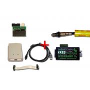 Full House DIY Tuning Kit$499 – $649 inc. GSTThis Full House DIY Tuning kit contains everything you need to DIY tune your own EA-AU Falcon! Includes a blank J3 Chip, J3 Programmer, TechEdge Wideband O2 Controller & LSU 4.9 Wideband O2 Sensor.
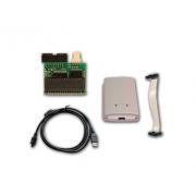 J3 Chip and Programmer Kit$299 – $429 inc. GSTThe T.I. Performance J3 Chip and Programmer kit gives you the ability to do your own custom tuning on your E-Series Falcon.
Trip Computer Wiring (where fitted)
If you have a trip computer fitted to your vehicle, the wiring must be slightly changed to suit the EL ECU. It can stay this way if you switch back to the EA-ED ECU.
- Remove the kick panel for access to the ECU loom.
- Locate the wire on Pin 34 (PWM Output). You will need to cut this wire.
- Locate the wire on Pin 58 (Injector Pulse).
- Join the wire (from the engine side) which went to Pin 34 of the ECU to Pin 58. Tape off the ECU side wire, it is no longer needed.
After this, the trip computer should operate correctly. Credit to this Fordmods for this fix. See here for EL ECU pinouts and here for EB ECU pinouts.
Recirc Door Wiring (Non Electronic Climate Control only)
Due to a change in the way the EEC can override Recirc mode in later manual climate cars, a small change must be made to the wiring to re-enable normal recirc door function. The wire to Pin 32 should be cut and taped to re-enable normal recirc function. Thanks to EB Pete on www.boostedfalcon.net for this fix.
Thermo fan Control
One optional feature when running an EL ECU is to enable control of EL Thermo Fans. Parts required:
- Installed EL ECU
- Spare ECU connector teminals (x2)
- EL Thermo fans
- EL Thermo fan Relay Unit (located behind passenger headlight) inc loom to batter (not required if you make your own custom loom)
The simplest way to get them running off the EL ECU is to take the fans & relay unit (including its loom) from a wrecked EL. You will need to wire a 40A fused lead to the positive connection of the relay unit, and also a solid earth. You will need to run two wires to the ECU to switch on the fans:
- ECU Pin 33 Fan Output 2 – To switch relays 2 & 3
- ECU Pin 53 Fan Output 1 – To switch relay 1
See here for thermofan wiring information, here for EL ECU pinouts and here for EB ECU pinouts.
BBM Control
Adding the later model Broadband Manifold (BBM) has many advantages, including better bottom end torque from the dual-runner configuration, and the ability to run late model belt drive (serpentine) and late model airbox (larger filter area). While a BBM can be fitted without an EL ECU, you will find issues with detonation as the timing maps need to be altered to suit the different runner length. The EL ECU solves these plus adds a terminal to operate the runner switch.
Parts required:
- EL ECU (installed as above)
- Spare ECU connector pin x 1
- Installed BBM
- BBM Solenoid (located behind washer bottle) inc. vacuum hoses and 1 way valve (IMPORTANT!)
You will need to install the BBM Solenoid behind the washer bottle (or elsewhere if you have Cruise Control). Ensure you have correctly connected the one-way valve in-line to the solenoid vacuum. You will then need to run an ignition switched positive for the solenoid, and a wire to the ECU as below:
- ECU Pin 15 – BBM Output (>3800V 12V)
See here for EL ECU pinouts and here for EB ECU pinouts.
Power/Economy Switch
The operation of the Power/Economy mode switch and dash light for the gearbox is reversed when fitting an EL ECU into an EBII-ED with EEC based transmission control.
Happy Tuning!
")


Leave a Reply
Want to join the discussion?Feel free to contribute!