J3 Chip Installation Instructions
This guide describes how to install a T.I. Performance J3 Chip into your ECU.
Please take the time to read this guide completely. Follow all the steps to ensure trouble free operation of your chip. Most problems can be traced to not following the instructions!
If you would like us to install and test your chip we can do this for a fee.
Required Tools: Philips Head Screwdriver, Flat Blade Screwdriver, 10mm socket, 7mm socket, 600 grit sandpaper, Methylated Spirits.
J3 Chip Installation Steps
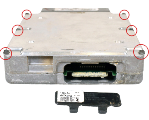
- Remove the passenger side kick panel and unscrew the ECU retaining bracket.
Note: In AU vehicles, this bracket is bolted in with a shear bolt – you will need to cut a slot to unscrew, or drill/punch out the bolt, which can be replaced with a screw. - Unbolt the ECU connector using a 10mm socket and remove the ECU from the car. Pry off the cap which covers the J3 port on the bottom of the ECU. Note on EB-ED V8 ECUs there is a screw and sticker which must be removed.
- Remove the 6 bolts around the edges of the ECU to remove the ECU covers and allow proper access to the port on both sides. The back cover may require a tap to remove.
- Wipe off the white paste (where present) with a rag and methylated spirits or isopropyl alcohol.
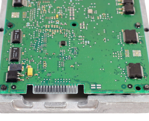
- Using a 3-4mm flat bladed screwdriver only, gently scrape off the clear conformal coating from the J3 port terminals by running the screwdriver in the direction shown in the photo below until all clear is removed. Scrape up and down the whole length of the terminals until all coating is removed from and in between each terminal. You should be left with a smooth, silver terminal all the way up to the green section of the board. You must do this on both sides of the J3 port.
- Note: This is the most important step of the process! Failure to follow this step correctly will lead to issues with operation of the chip!
- You must remove ALL imperfections or glossy coating until you have a completely flat surface when you run your finger down the port. Zoom in to the photo below to see the clean, dull surface.
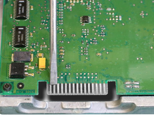
- Once you are sure have removed all of the clear coating with the screwdriver, use 600 grit sandpaper to lightly scuff the terminals, no more than 1 or 2 scuffs. Do not over sand, or you will remove the protective silver coloured solder. Finally, give the terminals a wipe with some methylated sprits or isopropyl alcohol to remove any oils or residue and ensure the best possible electrical contact.
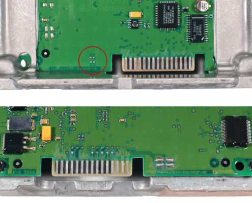
- AU Series 1 only. If your ECU is missing two small black resistors between the pads circled in the picture on the top side of the board, you will need to join the J3 Enable links on the back side of the board as shown in the Figure 4 for the J3 port to detect the Chip.
- This process will need to be done by someone familiar with soldering components on circuit boards, using a temperature-controlled iron, single strand wire, and flux core solder.
- Carefully clean the solder pads with 600 grit sandpaper, then use single strand wire to join each horizontal pair as in the bottom half of the image. Do not join the vertical pairs or scratch between the terminals or you could permanently damage the ECU.
- Tip: Use the Zoom function to see the photos more clearly.
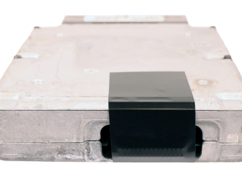
- Screw the covers back on the ECU. Hold the ECU with the label and screws facing up and insert the J3 Chip as shown in the picture.
- Note: Early V8 ECUs will require the tin cover to be cut and a capacitor to be bent over slightly to make room for the J3 Chip.

- Use our Clip In J3 Chip Cover that you can 3D print or purchase to secure the chip in place. If you do not have one, a strip of gaffer or duct tape can secure the chip in place and insulate the open terminals on the bottom of the unit, as shown in the photo on the right.
- Note: This step is essential for reliability. Vibration or movement of J3 Chip while the car is running will cause failure of the chip and/or ECU. Do not leave the Chip unsecured.
- Install the ECU back in the car and replace the retaining bracket and kick panel.
Read this before starting the vehicle
- Remember to never touch, move or remove the J3 Chip while the ignition is On. See step 9 for how to secure the chip in place.
- Turn the ignition to On, leaving the engine Off. Listen for the fuel pump — you should hear the regular 1 second priming of the fuel pump. If the pump stays on constantly, or does not start at all, the car is in LoS mode. Repeat step 5 before continuing.
- Start the car and get it to operating temperature. If you have issues with starting, idle, including rev hang, high idle or hunting, see the Troubleshooting section.
- Reset your base ignition timing (distributor models) to the factory setting for your ECU in timing/diagnostic mode. This is critical if you have previously dialled in any advance on the distributor, as the tune on your chip assumes factory base timing and idle screw settings. Click the link above for more information on how to reset your base timing.
Troubleshooting
- If the car runs rough, blows black smoke or is stuck in 3rd gear with the chip installed, check whether the fuel pump runs constantly with the Key On Engine Off. This indicates the ECU is in LoS mode. In most cases this is caused by the J3 port not being properly cleaned. Please repeat step 5, and then repeat the test before continuing. If the fuel pump is stuck on with the chip removed, you likely have a faulty ECU.
- If the car starts but you have issues with idle (including high idle, low idle, rev hang, hunting or stalling), your base idle will need to be adjusted. With the car at operating temperature, your chip installed and the ISC unplugged, adjust the throttle stop screw on the throttle body until the car idles between 500-550rpm (or as close as possible if a large camshaft is installed). You may need to turn this in a couple of screws to get a steady idle with the ISC unplugged. Also check the intake manifold gasket, injector o-rings and all hoses thoroughly for vacuum leaks. Modified throttle bodies and leaking intake gaskets are a prime culprit excess air, leading to rev hang and hunting.
- AU Falcon Only: If you fit the chip and your car does not crank, do not attempt to start the vehicle more than 3 times consecutively with the chip installed. Doing so will immobilise the car, which will require an OBD2 Scan tool and Forscan to do a PATS Reset to run again without a chip. Remove the chip and start the car normally to reset the failure count, then revisit steps 5 and 6 to make sure the J3 port is enabled and clean before trying again. If the Smartshield hand on the dash is flashing fast and the car won’t crank with the chip removed, the car has already been immobilised, however the chip will still disable Smartshield once installed properly.
Still having trouble?
If you still have trouble getting your vehicle running correctly after following this guide, reply to your order email with all four of these things:
- clear photos of your ECU, showing the J3 port itself and the whole ECU, from both sides, with the covers off, and J3 chip removed,
- acknowledgement that you followed these instructions and have read this step,
- a detailed description of the problem you’re experiencing, including what the fuel pump does with the key on engine off, and
- confirmation that the mods on the car match the tune notes in your order email.
Including these things in the first email will allow us to diagnose the problem quickly. If you do not include them we will just refer you to this guide.
If you would like us to install and test your chip we can do this for a fee.
Please contact us before posting on Facebook! We have been working with these ECUs for almost two decades. We will get you up and running faster than anyone else.